Chapter 5 - Gull Wing Canopy
Section 1 - Fabricating Canopy
Frame Outer Skin Parts
To create our canopy frame skin parts we will need to be familiar with the poor man's vacuum bagging technique. If you do not want to use vacuum, the method is simplified in that you will only use a plastic film to protect the canopy, then squeege the wet layup directly onto this plastic film and let cure. Follow the instructions here for the proper size of the layup.
Once all seven skin parts are fabricated, each piece will be trimmed to size. We will add the internal foam structures and layup the internal skin. At this point the canopy frame is very ridgid and we can cut out the door frames from the stationary frame. We will attach the stationary frame to the aircraft. We will install the hinges, latches and Plexiglas for a finished canopy.
The canopy frame will be made from seven individual parts, all using carbon fiber. Again let us review the seven parts we are going to fabricate:
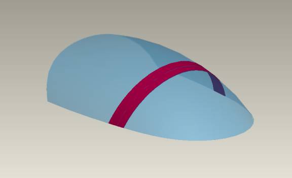
- Canopy Roof
- Two Rear Pilliar Bows
- Two Windshield Bows
- Two Door Bottoms
The canopy roof will be fabricated first.
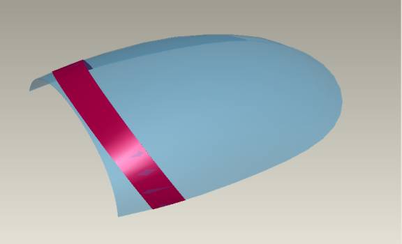
Identify the area of the canopy we want to use as our mold. We want the roof to be 14 inches wide and extend from at least the rear most line defining the windsheild bow all the way back to the rear of the canopy. If not using vacuum, protect the inside of the canopy with a sheet of plastic drop cloth. Pull the drop cloth tight in all directions with tape attached to the wooden support structure. If wrinkles are left in the plastic sheet, they will be transferred to your finished part. Since we are not using vacuum, there will be some wrinkles transferred, but try to minimize them now.
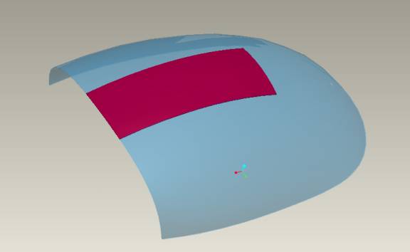
Desired Roof Section
The roof section we want is shown above and is defined by our tape markings made earlier.
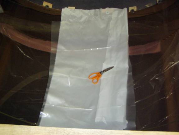
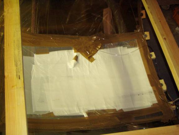
Tool Side Bleeder
Cut the Clean the area with rubbing alcohol that the tape will be stuck to and wipe the surface with a tack rag. Any grit or debris left on the surface will be transferred to our part and can easily puncture our bagging film. Clean an area about two to three inches wider than the actual part all the way around, and about 6 inches wider on one side-the side we plan to place our vacuum coupler. Cut a piece of Peel Ply about an inch wider than our finished part all the way around.
Using small pieces of tape position this against the mold (the tool in vacuum bagging parlance). Decide where the vacuum coupler will be located; in our example we will place it in the middle of the long side of the part. It needs to be placed well away from the part so we can have a smooth surface to tape our bagging film to later.
Next, cut a piece of plastic drop cloth large enough to surround the peel ply and incorporate the area where the vacuum coupler will be while still allowing at least an inch of tool surface all the way around the plastic to allow us to tape it down. Trial fit it to the area allowing a little slack so the plastic is not too tight when sucked down with the vacuum.
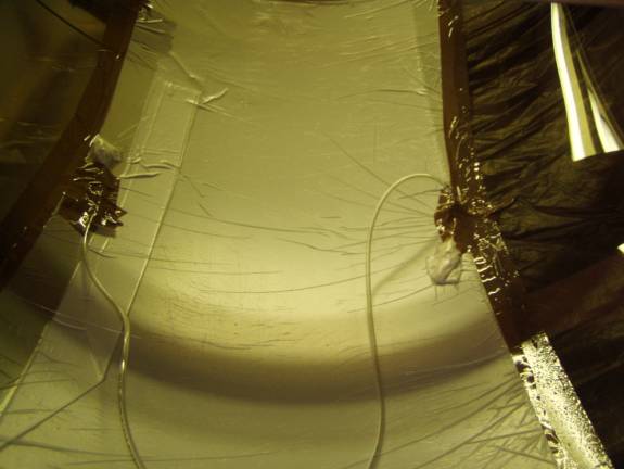
Tool Side Bleeder under vacuum
Go ahead and install the coupler as described earlier. Now, using small pieces of tape locate the sheet of plastic in place. When satisfied with it’s positioning, use packing tape to secure the outside edges to the tool. Try not to get any wrinkles along the edge where the plastic is secured as these wrinkles can leak air. When all is secure, slowly apply a vacuum to the bag and see if it pulls down tight.
There will be wrinkles in the plastic against the tool; releasing and reapplying the vacuum and working them off to the edge of the plastic with a squeegee can work these out. Be very careful not to puncture the plastic as you do so. Take a sharpie marker and mark an outline of the exact location of the part you want to create. This will make placing the layup go quicker when you are ready.
Congratulations you have created a tool side bleeder. The surface is ready to accept your wet layup. Leave the vacuum running to insure the integrity of your tool surface and prepare your layup.
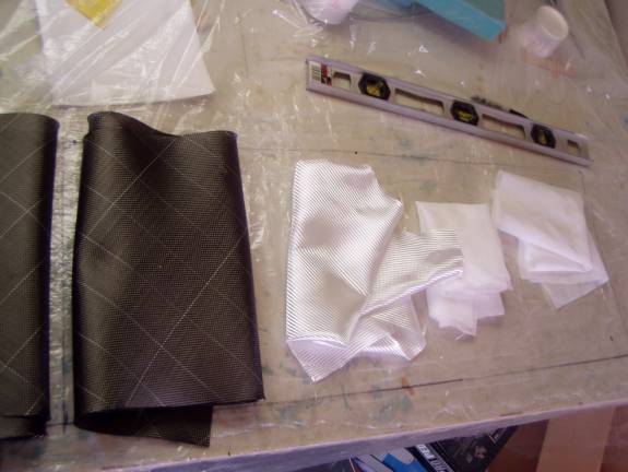
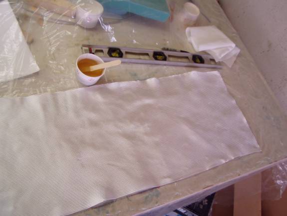
Preparing Cloth for Layup
Layout an oversized sheet of plastic on your work table roughly 24 inches by 48 inches. Using a sharpie, draw a 14”X44” rectangle on the plastic. The layup will be make on this sheet and the whole thing will be transferred as a unit. Cut out two pieces of carbon fiber, 1 piece of BID and two pieces of peel ply.
Fiberglass Cloth toward Outside
First place a layer of Carbon Fiber on the plastic sheet, then wet out thoroughly. Place the second layer of Carbon, wet thoroughly and work out all the air bubbles. Carbon is a little harder to work with in that you can not see through it. You must insure that it is completely wet and there are no air bubbles. Finally add the layer of fiberglass. This last layer will be placed directly to the tool side bleeder so that the outside skin is fiberglass, not carbon. Then use the same rigor and add the second layer of carbon. At this point we need to insure that we have fully wet the layup stack and removed all air bubbles. It is better to err on the side of a bit too much resin as we will now take paper towels and soak up the excess. Do not apply localized pressure, with a fingertip for example, but uniform pressure with a roller or a wide brush.
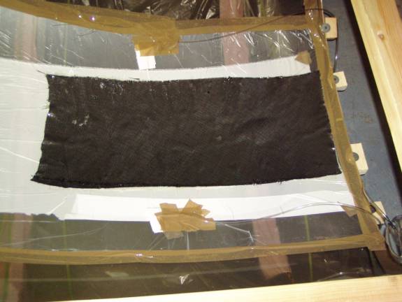
Carbon Fiber Layup
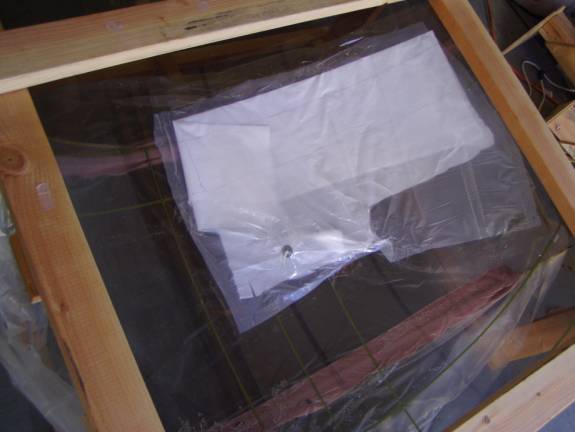
When you are happy with the layup, transfer it to the center of the canopy. It is placed onto the canopy running along the top aligned with the rear of the canopy. It does not need to be make it all the way to the front tape line in front of the windshield, but it needs to over hang the rear most tape line marking the windshield. Smooth it out against the shape of the canopy. This will take a bit of time as the multiple layers will have to shift a bit to accept the compound curved shape.
Apply sections of peel ply to the top of the set layup. The shape we are making consists of compound curves so it is better to use several smaller pieces of peel ply to completely cover the layup. Carefully press these into the layup without disturbing its position.
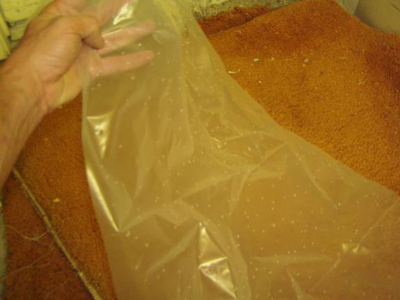
Pourous release film
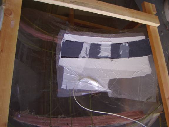
We will place a layer of porous release film roughly the same size as the part we are making on top of the peel ply. This will make it easier to remove the bleeder material when our part is cured. Take a piece of our 2 mil drip cloth material and cut out a piece the slightly larger than the layup. Now take this piece of plastic and lay it a carpeted surface and perforate it with a small finishing nail. Punch a bunch of holes in the plastic sheet until you have a grid of holes roughly every ½ inch to 1 inch. Place this over the peel ply with the punctures pointing up.
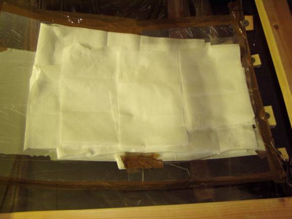
We now want to cover the porous release film with a bleeder material. I use a discarded mattress pad, and I have also used about four of paper towels. For this discussion let us assume we are using paper towels—after all this is the Poor Man’s Technique. Roll out at least four layers of paper towel over the entire layup, but do not extend past the edges of the porous bleeder and layup. This layer does not have to be organized neatly, just make sure there is enough to cover the porous release film.
Next, cut a piece of plastic drop cloth large enough to surround the layup allowing at least an inch all the way around the plastic to allow us to tape it down. It should remain clear of the vacuum coupler used for the tool side bleeder. Trial fit it to the area allowing a little slack so the plastic is not too tight when sucked down with the vacuum. Use a sharpie marker to mark the location of the coupler. In this application I put the vacuum couple right in the middle of the part. Generally this is not a good practice, as the couple will make impressions on the finished part. Since the surface we are working on will end up being the inside of a glass and foam sandwich this is not an issue. I am more interested in minimizing the size of the vacuum bag and getting the vacuum coupler centered on the part.
When satisfied with the vacuum bag’s positioning, use packing tape to secure the outside edges. Try not to get any wrinkles along the edge where the plastic is secured as these wrinkles can leak air.
We are ready to apply vacuum to the outside bag. You can use a length of polypropylene tubing as a stethoscope to search out air leaks. Hold one end of the tube near your ear and use the other end to search the bag for hissing. Iron these down with your thumb or apply more tape over them. In some case they may be so sever that you will have to start over. Take the time to do so.
Let the layup cure for about half the total cure time, in my case about 6 hours. I have a fan blowing on my vacuum pump, as it can get quite warm over such a long time.
Congratulations, you have completed the first part made using your canopy as a mold. You now have the technique down and the remaining parts will be done in a similar manner.
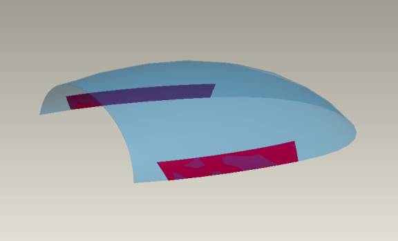
The next part to be fabricated is the windshield bow. This is done in two sections, each side of the center line. Create a layup sandwich 7 inches wide and 24 inches long using the same layup schedule as before for each side.
Windshield Bow
Windsheild bow tool side bleeder
Windsheild bow layup ready for vacuum bagging.
The next parts to be fabricated are the rear canopy bows. These are the pieces that form the rear side of the canopy doors and the front edge of the turtle deck.
Rear Pillar Bow
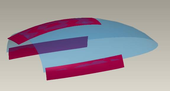
If the canopy rear frame is made in two pieces, each is made from a layup sandwich of 6 inches wide by 30 inches long and is laid in the position marked on the outside of the canopy earlier.
Door Frame bottom pieces
The last two pieces that are fabricated are the bottom of the canopy
door frames. These pieces are made by running a layup along the
bottom of the canopy 7 inches tall. It is important that the layup
runs from the rear most line forming the rear canopy bow to the forward
most line marking the front of the windshield bow. This is important,
as this part will fill the gap between the fuselage side and the Plexiglas
canopy.
The fabrication of the door frame bottom pieces are described in more detail in the poor man's vacuum bagging section.
Trimming to Proper Size
When all seven parts are cured they are trimmed to proper width. Remember that the parts should be trimmed to their final symmetry. For example, the first part that was made runs along the top of the canopy. This part will be trimmed to a final width of 12 5/8”. If the initial part was 14 inches wide, trim equal widths from each side so the resulting part is still centered on the center line of the canopy and aircraft. The windshield bow parts are trimmed to a final width of 5”, the canopy frame bottom sections are trimmed to a final width of 6.5” and the rear canopy frame sections are trimmed to 6 inches.
Slide Sides down three Inches
Once all of the parts are trimmed to their proper width, it is time to trim them to match each other. The roof section is placed back in the center of the canopy; again remember that the canopy must be covered with a protective plastic sheet. The front edge of the roof section is trimmed to the back most line defining the windshield bow. The two canopy door sides are remounted to the canopy, but are mounted three inches low. Look at the above photo and see how the canopy sides appear to have slid down. It is these pieces that fill the three-inch gap between the canopy and our fuselage side. Trim the windshield bows to match each other (if you made the windshield bow in two parts) and trim to match the top of the canopy door sides.
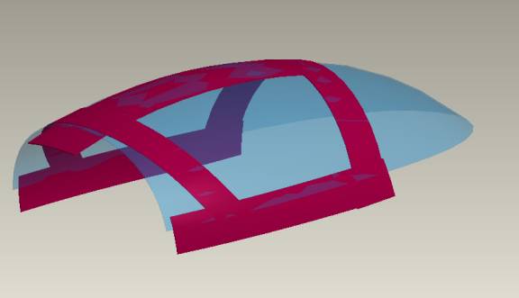
Lay the front and rear bows in place.
The rear canopy pillar pieces are moved rearward three inches. Trim the roof part so it matches the rear pillar bow. Trim the rear pillar bows so they match the top line of the canopy side parts. Finally trim the rear edge of the canopy side parts to match the curve of the rear side of the rear pillar bows. You should end up with parts that when joined together look like the following photo.

Full Frame Outer Skin Parts Aligned.
Congratulations you have completed the full set of parts that will become the outer skin of the gullwing doors and their frame. We are now ready to begin bonding these parts together to create the complete outer skin assembly.