
Poor Man's Vacuum Bagging
I have been experimenting with vacuum bagging to create the parts required for the gull wing canopy. I use the full size Plexiglas canopy as a mold and use vacuum bagging to suck the wet carbon fiber layups down against it to create the frame. These parts are relatively small—typically about 6 inches wide by about three feet long—and lend themselves to a small-scale vacuum bagging technique.
I found a relatively inexpensive way to vacuum bag, and out of this experience I have documented this ‘Poor Man’s Vacuum Bagging’.
Materials Required:
- Vacuum Pump
- Vacuum Gauge
- Run of the Mill 2 mil plastic drop cloth – lot of it
- Peel Ply
- 3/16” O.D. nyflow tubing
- 3/15” O.D plastic tubing
- 3/16” plastic tee fittings
- ¼” 90 degree plastic fittings
- Rolls of Paper Towels
- Rolls of Packing Tape – lots of it
- Duct Tape
- Fender Washers
- 5 Minute Epoxy and Flox
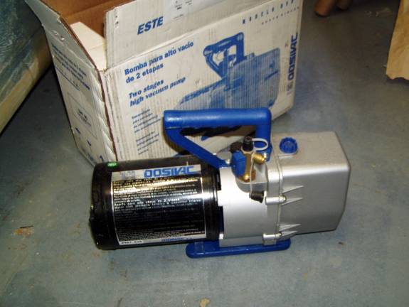
Vacuum Pump – I went through three, increasingly expensive, vacuum pumps before I found one that worked well for my application. There are two parameters that are important in a vacuum pump, how hard of a vacuum the pump can pull measured in inches of mercury, and the amount of air the pump can move measured in cubic feet per minute. I found that for effective vacuum bagging you need a pump that can pull a hard vacuum—better than 25 inches of mercury and that the pump can move a decent amount of air—say at least a couple CFM. First I used a vacuum pump out of an old refrigerator. I found that it could pull a decent vacuum, but it had a very low CFM rating and even a tiny leak killed my vacuum. (Another thing I learned, it is almost impossible to create a leak free vacuum bag set up). The second pump I bought was a two stage oilless pump that claimed to have decent specs, but upon actual application could not pull down more than about 10 inches of mercury against just a vacuum gauge—very disappointing. The third and final pump that I tried was one designed for evacuating automobile air-conditioning systems. It uses oil and is able to pull a very strong vacuum. The CFM rating of my pump is only 3 CFM, but I was able to get it to work quite well. It only cost $130 new on ebay and there were lots of them.
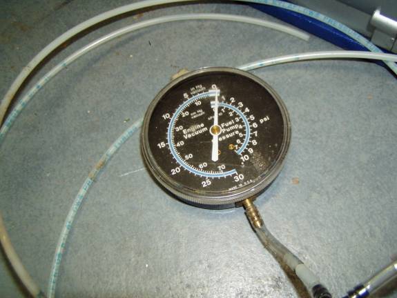
Vacuum Gauge – I am using a combination vacuum/pressure gauge I picked up at the auto parts store for $10. It reads down to 30 inches of mercury and seems to work fine. It has a brass 3/16” barb fitting on it that mates with the rest of my hosing connection scheme.
2 Mil Plastic Drop Cloth – I use this plastic for everything—Breather Ply, Bleeder Ply, vacuum bagging Film, release Film, porous release film. The only modification needed is punching of holes in a piece that is to be used for porous release film—more on this later.
Nyflo Tubing – This is nice tubing for vacuum as it does not collapse under a strong vacuum.
Polypropoleen tubing – this tubing is too soft to be used as general purpose tubing because it will collapse under a hard vacuum, but it is pliable and works well to join the nyflo tubing to our tees and the vacuum couplers on the bag.
Tees - All tube on three sides (ACS 0715-011) allows us to tee off the vacuum gauge and multiple vacuum ports in our vacuum bag.
Packing tape – I prefer the brown packing tape as it is easier to see against the clear plastic film (2 mil drop cloth). The clear packing tape works just as well.
Duct Tape – There are a few applications that the more pliable duct tape is a superior solution to the packing tape, it is more expensive, but we don’t need much. Attaching the vacuum coupler to the vacuum bag is the prime use of duct tape.
Fender Washers – these are used in conjunction with the 90 degree ¼” plastic fittings to make our vacuum couplers. This device is very critical as the point that the hose is attached to the vacuum bag is the most difficult point to seal.
5 minute epoxy and flox – We use this mixture to mate the 90 degree ¼” plastic fittings to the fender washers to make our custom, low cost vacuum couplers.
Vacuum Bagging Basics.
Definitions:
Tool – the thing we are using as a mold
Bleeder – a carrier and holder of excess resin in our vacuum bag
stack up.
Peel Ply – a nylon material that serves as a release agent against
the carbon fiber layup.
Vacuum Coupler – a way to attach a vacuum hose to our vacuum bag.
Bagging Film – the plastic the vacuum bag is made out of
Release Film – the plastic that is placed between the mold and
the wet layup that allows us to separate the cured part later and is
used to protect the mold surface.
Perforated film – a layer of release film that allows the resin
to pass through, but does not stick to the cured part or the bleeder
material. This is placed between the wet layup and the bleeder
material.
In its simplest form vacuum bagging actually uses a plastic bag-thus its name. In this simplest case, we enclose our wet layup in a sealed bag against our mold. We evacuate the air and let the atmospheric pressure press the wet layup against the mold and let it cure. There are some problems with this simple case, of course, we don’t want the layup to stick to the mold and we would like to have some mechanism to soak up the excess resin. The ‘sticking to our mold’ problem is resolved by using plastic film between the mold and our layup. To soak up excess resin the fiberglass layup is covered with peel ply, a porous release film, and a layer of bleeder material. This complete stack up is then placed in a sealed bag and a vacuum is applied to the bag. Atmospheric pressure squeezes the fiberglass layup, the excess resin is pressed out of the layup, through the peel ply, through the porous film and into the bleeder material. The vacuum is held in place until a solid cure has set in, typically ½ the total cure time, in our case about 6 hours.
Tool Side Bleeder
In using vacuum bagging to build the frame for our gull wing doors, we cannot put the complete canopy in a bag, so we need to use sections of the canopy as our mold in multiple iterations. To insure that the plastic release film is held tight against the canopy, we use a technique referred to as a tool side bleeder.
We will be using two bags. One containing only a thin bleeder layer and the second containing the wetted carbon fiber. This first bag is our tool side bleeder and is used to pull the release film down tight against the tool surface. The second bag is taped down on top of this in the traditional manner.
Let us take a complete example all the way through. We will be making the lower side of our canopy frame. To do this we will be using the lower section of the Plexiglas canopy as our mold. Let us set up our equipment first.
Vacuum Pump and tubing. We want to end up with three attachment points to our vacuum pump, one for the tool side bleeder, one for the vacuum bag and one for the vacuum gauge.
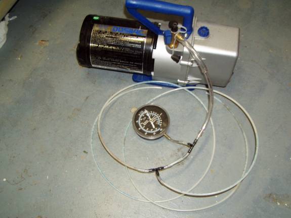
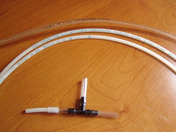
Pump with hose fittings to two Tees
Pictured above is my vacuum pump with an arrangement of tubing to get me two points for vacuum and a gauge. I use a fan blowing on the vacuum pump as they are not intended to be run for as many hours as we require. Also the exhaust air from the vacuum pump is laden with oil vapor so I vent it outside and filter it through a bucket of soapy water. On the end of the hose I tied an old sock to atomize the air and put it in a bucket of soapy water. The soap in the water tends to trap most of the oil vapor.
Building the Vacuum Couplers
The trick to successful vacuum bagging is as good a seal around the bags as possible and the most difficult place to do this is the vacuum coupler. The vacuum coupler is the point where the vacuum line is attached to the bag. Let us make a coupler.
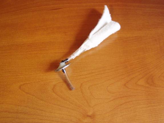
A Completed Vacuum Coupler
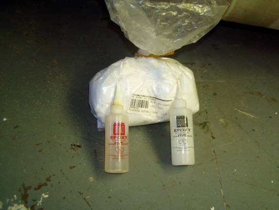
The parts required to make our vacuum coupler: a fender washer, a 90 degree tee, a couple pieces of soft tubing, a small piece of nyflo tubing drilled, a piece of bleeder material, five minute epoxy and flox. Test fit the 90 degree ¼” plastic fitting through the hole in the fender washer. Now mix up a little 5 minute epoxy with some flox added and smear it on the side of the washer that has the tee bend in it. Do not get any epoxy on the tee’s barb and allow enough room for tubing to be slid on later. The hole should be completely sealed and the epoxy around the tee should have no pin holes. The other side of the washer should have no trace of epoxy. Let this cure.
Now slip on short sections of polypropylene tubing to act as couplers to our nyflo tubing. Take a small section of nyflo tubing, about 4 inches long and drill a series of small holes perforating about an inch of one end of the tubing. Wrap a small piece of bleeder material around this end and slip the other end into clear tubing coupler on the side of the vacuum coupler that has the epoxy on it. You have a completed coupler. All we need is a piece of duct tape to seal it to a vacuum bag.
To install a coupler to the bag, remove the short perforated tube with the bleeder head. Carefully cut an X into the bag with legs of about 3/8”. Insert the coupler through this cut from the top of the bag, epoxy side down. Cut a square piece of duct tape as large as the width of your tape will allow. Cut a ¼” hole in the middle of the tape and slide this down over the top of the coupler and secure the coupler to the bag. Use a hand on top and a hand underneath to smooth out the bag at the joint and don’t allow any wrinkles. Work the duct tape into the plastic bag and the coupler to get a good seal.
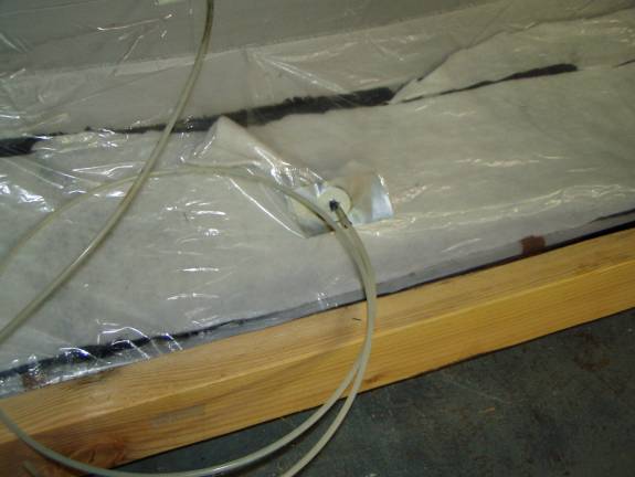
Setting up the tool side bleeder
We are ready to set up our tool side bleeder. The part we are going to be making for this example is the bottom edge of our canopy frame. Ultimately this part will be cut into two and will result in the outside skin of the lower canopy frame along the top of the fuselage and the lower part of the canopy door carrying the Plexiglas. This part is about 8 inches tall and 33 inches long. We will not worry about the creation of the layup here, only the vacuum bagging technique that will surround it.
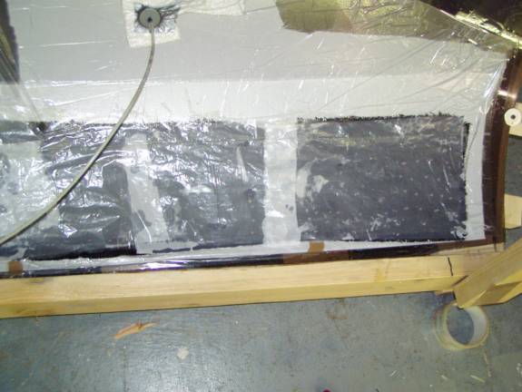
First identify the area of the tool we want to utilize. In our case it will be the bottom edge of the canopy that rests against the fuselage. Clean the area with rubbing alcohol that the tape will be stuck to and wipe the surface with a tack rag. Any grit or debris left on the surface will be transferred to our part and can easily puncture our bagging film. Clean an area about two to three inches wider than the actual part all the way around, and about 6 inches wider on one side-the side we plan to place our vacuum coupler. We are limited on the fuselage side as we have a wooden support structure in our way. Cut a piece of Peel Ply about an inch wider than our finished part all the way around.
Using small pieces of tape position this against the mold (the tool in vacuum bagging parlance). Decide where the vacuum coupler will be located; in our example we will place it in the middle of the long side of the part. It needs to be placed well away from the part so we can have a smooth surface to tape our bagging film to later.
Next, cut a piece of plastic drop cloth large enough to surround the peel ply and incorporate the area where the vacuum coupler will be while still allowing at least an inch of tool surface all the way around the plastic to allow us to tape it down. Trial fit it to the area allowing a little slack so the plastic is not too tight when sucked down with the vacuum.
Use a sharpie marker to mark the location of the coupler. It may be easier to install the coupler at the comfort of your workbench instead of over the tool.
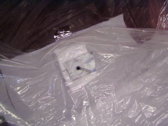
Go ahead and install the coupler as described earlier. Now, using small pieces of tape locate the sheet of plastic in place. When satisfied with it’s positioning, use packing tape to secure the outside edges to the tool. Try not to get any wrinkles along the edge where the plastic is secured as these wrinkles can leak air. When all is secure, slowly apply a vacuum to the bag and see if it pulls down tight.
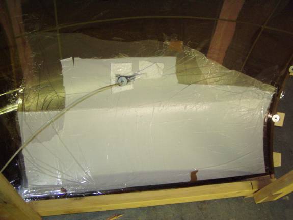
There will be wrinkles in the plastic against the tool; releasing and reapplying the vacuum and working them off to the edge of the plastic with a squeegee can work these out. Be very careful not to puncture the plastic as you do so. Take a sharpie marker and mark an outline of the exact location of the part you want to create. This will make placing the layup go quicker when you are ready.
Congratulations you have created a tool side bleeder. The surface is ready to accept your wet layup. Leave the vacuum running to insure the integrity of your tool surface and prepare your layup, in our case it will be a layer of BID fiberglass and two layers of BID carbon fiber with the fiberglass applied against the tool (the ultimate outside surface of the canopy frame). When preparing the layup use the plastic sandwich technique, that is layup the carbon fiber between two layers of plastic that are cut to the same size as the final layup. This will make it easier to handle when moving from your work surface where the layup is made to the tool surface. We also do not want the layup to be dripping resin, as we will need a clean surface all the way around the layup to seal our tape.
Preparing the Vacuum Bag, Layer by Layer
Wet Layup
The creation of the fiberglass layup is described elsewhere and will not be repeated here. Let me just say for informational purposes that it consists of a BID fiberglass outer layer and two layers of BID Carbon Fiber. Transfer the wet layup to the tool surface and align it within the sharpie marks you have made earlier on the tool surface.
You should have removed one side of the plastic layup sandwich so the wet fiberglass is resting directly against our tool side bleeder. Leave the outer sheet of plastic on the layup sandwich while you use the squeegee to work the wrinkles and air bubbles out of the layup and position it within the sharpie marked line. When satisfied with the position of the layup, remove the outer layer of plastic exposing the wet carbon fiber layer. Again squeegee any air bubbles and wrinkles out of the layup, being careful to mop up any excess resin squeezed from the layup. When satisfied, use rubbing alcohol on a paper towel to clean the tool side bleeder all the way around the layup so we have a clean surface to tape our vacuum bag to.
Peel Ply
Apply sections of peel ply to the top of the set layup. The shape we are making consists of compound curves so it is better to use several smaller pieces of peel ply to completely cover the layup. Carefully press these into the layup without disturbing its position.
Porous Release Film
We will place a layer of porous release film roughly the same size as the part we are making on top of the peel ply. This will make it easier to remove the bleeder material when our part is cured. Take a piece of our 2 mil drip cloth material and cut out a piece the slightly larger than the layup. Now take this piece of plastic and lay it a carpeted surface and perforate it with a small finishing nail. Punch a bunch of holes in the plastic sheet until you have a grid of holes roughly every ½ inch to 1 inch. Place this over the peel ply with the punctures pointing up.
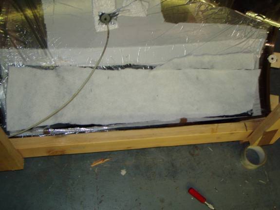
Bleeder Material
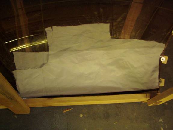
We now want to cover the porous release film with a bleeder material. I use a discarded mattress pad, and I have also used paper towels. For this discussion let us assume we are using paper towels—after all this is the Poor Man’s Technique. Roll out at least four layers of paper towel over the entire layup, but do not extend past the edges of the porous bleeder and layup. This layer does not have to be organized neatly, just make sure there is enough to cover the porous release film.
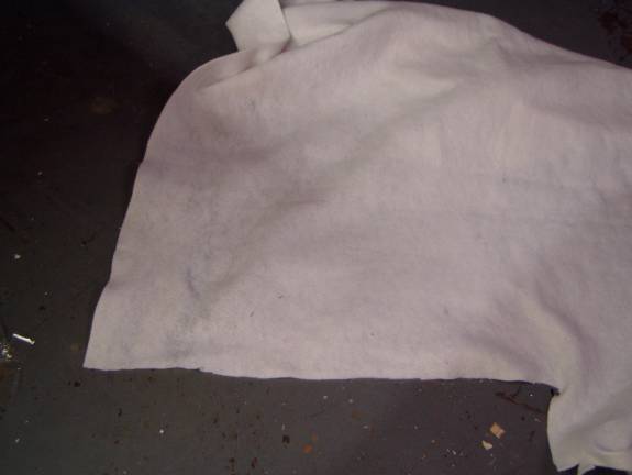
Mattress padding used for bleeder
Many materials work well for the bleeder layer—quilting material available at your fabric store is inexpensive and works well.
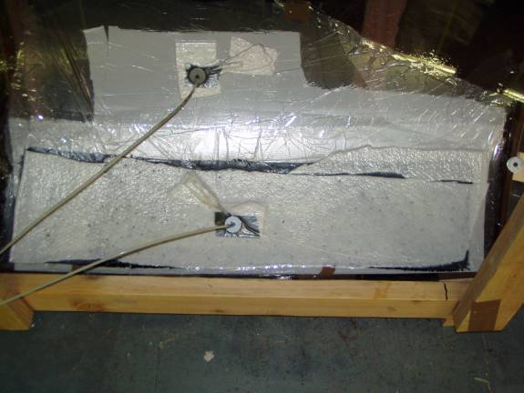
Vacuum Bagging Film
Next, cut a piece of plastic drop cloth large enough to surround the layup allowing at least an inch all the way around the plastic to allow us to tape it down. It should remain clear of the vacuum coupler used for the tool side bleeder. Trial fit it to the area allowing a little slack so the plastic is not too tight when sucked down with the vacuum. Use a sharpie marker to mark the location of the coupler. In this application I put the vacuum couple right in the middle of the part. Generally this is not a good practice, as the couple will make impressions on the finished part. Since the surface we are working on will end up being the inside of a glass and foam sandwich this is not an issue. I am more interested in minimizing the size of the vacuum bag and getting the vacuum coupler centered on the part.
It is easier to install the coupler at the comfort of your workbench instead of over the tool. Go ahead and install the coupler in the plastic sheet as described earlier. Now, using small pieces of tape locate the sheet of plastic in place.
When satisfied with the vacuum bag’s positioning, use packing tape to secure the outside edges. Try not to get any wrinkles along the edge where the plastic is secured as these wrinkles can leak air.
We are ready to apply vacuum to the outside bag. You can use a length of polypropylene tubing as a stethoscope to search out air leaks. Hold one end of the tube near your ear and use the other end to search the bag for hissing. Iron these down with your thumb or apply more tape over them. In some case they may be so sever that you will have to start over. Take the time to do so.
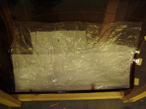
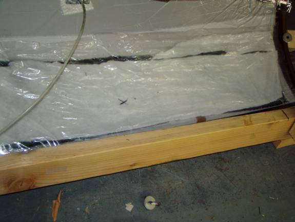
Let the layup cure for about half the total cure time, in my case about 6 hours. I have a fan blowing on my vacuum pump, as it can get quite warm over such a long time.
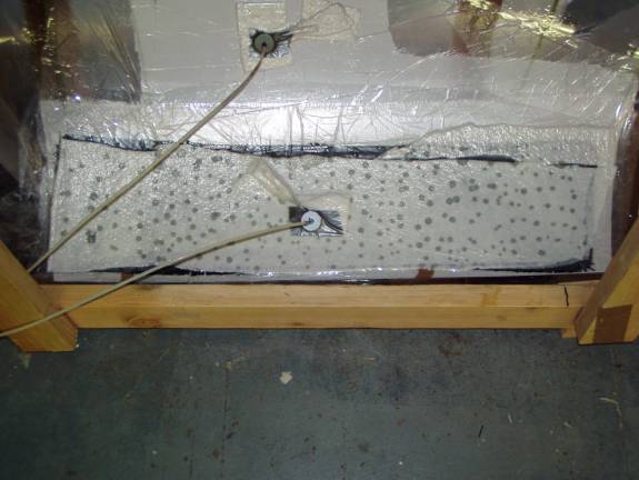
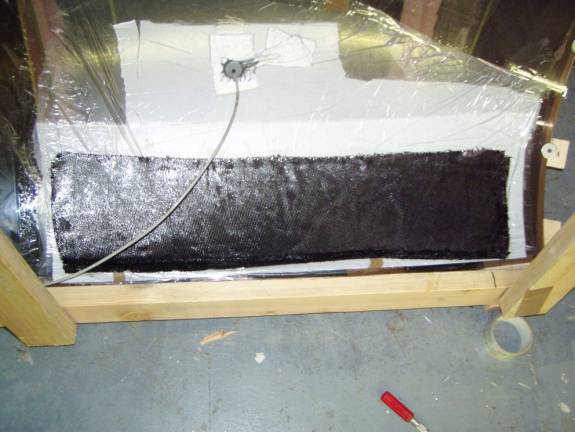
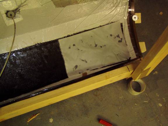
In the above photo you can see the vacuum pulling the bagging film tight into the weave of the bleeder layer and you can see resin being pulled through the porous film layer into the bleeder. Congratulations, you have created a fairly complex vacuum bagged part—in the tradition of the Poor Man.
.