Chapter 7 - The Wing
Section 1 - Spars
Outboard Spar construction
The wing for the Super 2 is built in three sections. This is done because of the limited space often available to the homebuilder. The wing can be completely detached from the fuselage allowing the wing and fuselage to be transported on a trailer with less than 8 feet overall width. The wing sections are a center wing section and two outboard wing panels. While building, the center section of the wing can be attached to the fuselage to allow for complete rigging of the electrical, control systems, fuel and pitot system. A single wing tip can be installed at a time and the aircraft will still easily fit in the garage.
The construction of the wing is very similar to that of the horizontal stabilizer and it is a good idea to refresh your memory by reviewing the horizontal stabilizer construction section. The two outboard wing panel spars will be constructed first and the builder will gain experience working with the Graphlite Pultruded Carbon Fiber material used in the spar caps and the use of phenolic as hardpoints. These spars are simple in their construction and they can be constructed on a flat table, but expose us to the construction of the main spar caps and the shear webs. Next we will tackle what could be the most exciting item in the aircraft—the wing’s main spar. We use a moldless techinge for building the spar; the spar shearwebs are built first and act the the forms for the sparcaps.
The wing ribs are constructed in the same manner as those in the horizontal stabilizer: we will fabricate flat panels of foam and BID, then cut out the ribs, then add a flange along the top edge. The ribs will have holes for control tubes, fuel and electrical.
The rear wing spars are very similar to the horizontal stabilizer spars with the exception of a few holes for control rods and the use of phenolic hardpoints.
Once these components are completed we will bolt the spars together and jig it into a stable level position. The ribs and trailing edge spars are bonded in place and the wing begins to take shape. We will bond the bottom skins in place then do some work in the fuel cells adding slosh gates, fuel screens and the fuel sender.
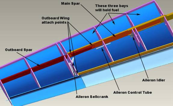
We will install the aileron bellcrank, aileron idler and the structure to support the main gear. There will be two access panels on each side on the bottom of the center wing section. One will be used to gain access to the aileron bellcrank for inspection purposes as well as to gain access to the wing attach bolts for the outer wing panels. The second access panel will be used as an inspection port for the gear attach fittings and the aileron idler. The most outboard panel also serves as the mounting point for the pitot. The left outboard wing panel also has a single removable panel for the mounting of the optional autopilot servo. The Super2 was designed to use the TruTrak or Dynon autopilot servos, but others may be adapted.
We will seal the fuel cells and then close the wing by installing the top wing skin. The flaps and ailerons are built in a manner similar to the elevator with a spar, ribs and solid foam blocks then covered in carbon fiber BID. A trim tab is installed in the left aileron and the control surfaces are attached and the ailerons are balanced with an outboard counterweight.
Lets get started.
First we will build the two outer wing spars. This will give us the skills needed to build the center spar section, but on a smaller scale. We will use pultruded carbon fiber in the spar caps and standard ½” 2.5 lb last-a-foam and BID fiberglass for the shear webs.
Materials required include:
1 sheet of ½” thick 4.5 lb. Last-a-foam
400 feet .070 X .437 Graphlite solid rectangle
BID Fiberglass
Epoxy
12” X 12” ½” thick phenolic sheet
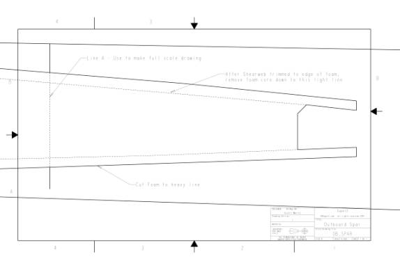
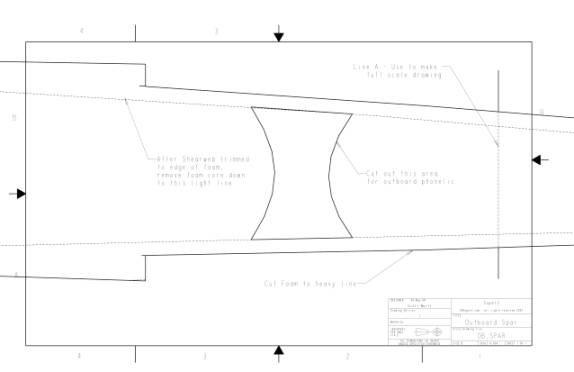
Print out the following three drawings: Dimensioned Outboard Spar, 1:1 detail A, and 1:1 detail B. Cutout and paste the detail A and detail B drawings together and use these as a template for the inboard section of the spar.
Use templates to create the inboard section of spar
Use the dimensioned drawing to create the full size spar out of ½” 4.5 lb. Last-a-foam.
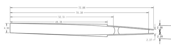
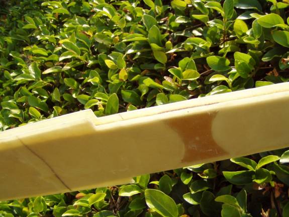
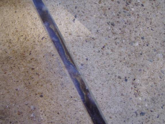
Use a long straight edge against the top and bottom edges to center the inboard section. Notice the 2.2" dimension in the photos below:
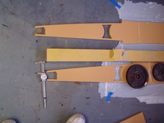
Center the inboard section between top and
bottom edge (2.2” from
projected line).
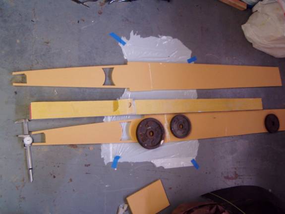
Straight edge projecting line from top edge
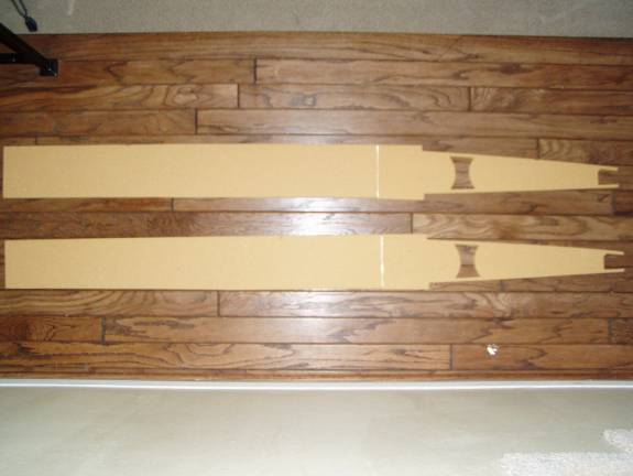
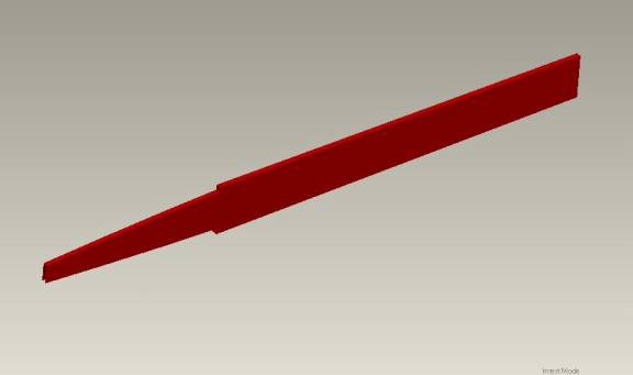
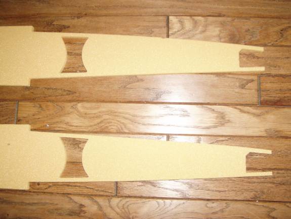
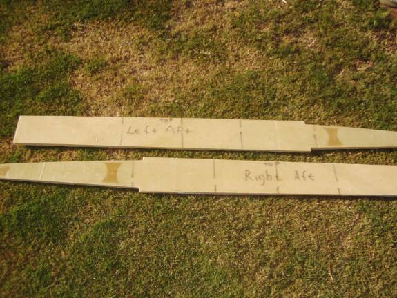
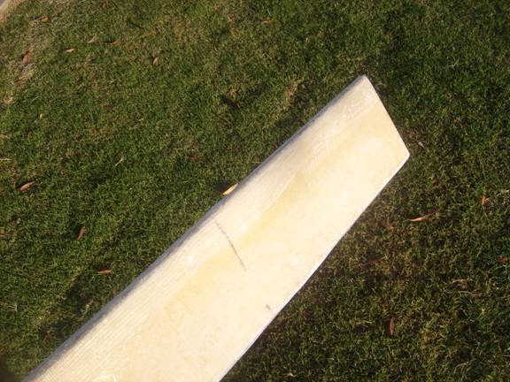
Completed Foam Spars
Printout the drawing for the two phenolic inserts and fabricate two of each. These will be made from ½” phenolic sheet. Use coarse sand paper on the order of 60 grit to completely roughen both sides of the phenolic. Drill the hole on a drill press to insure it is perpendicular to the surface.
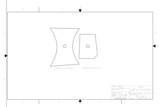
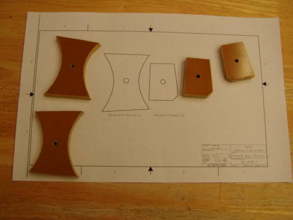
Cut two each phenolic using 1:1 template
Install phenolic in cutouts
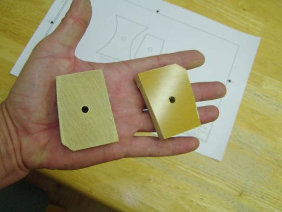
Roughen phenolic with coarse sandpaper (40 grit)
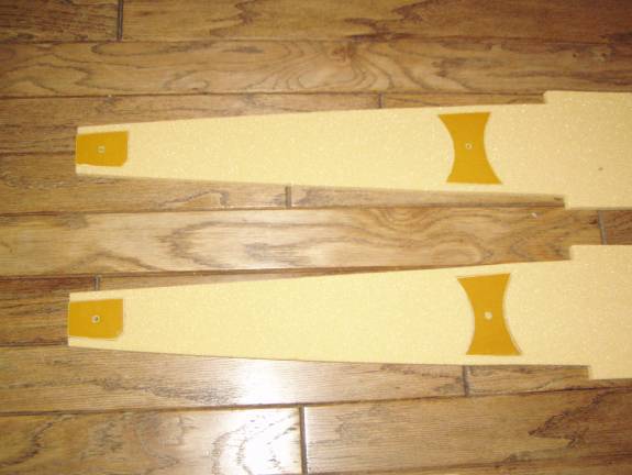
Lay the complete outboard spar foam blank on a table and bond in the two phenolic parts using a thick micro. You do not need to bond the top and bottom sides of the phenolic as this foam will be removed later. Do not get any on the outside of the phenolic, we need a good bonding surface to the BID shear webs. Mark the outboard spars as to right side, left side, front side, rear side, top and bottom. From this point forward we do not want to mix the spars.
Use the following layup schedule to create the front and back shearwebs from our standard BID fiberglass.
Layers Front Back
BID From
inboard edge From
inboard edge
_____________________________________________________________________
6 over the first 28
inches 22
inches
5 over the first 40
inches 35
inches
4 over the first 50
inches 45
inches
3 over the first 60
inches 55
inches
2 over the entire
length entire
length
First layup BID on the front side of the spars; do both at a time.. By this time you should know to vacuum and slurry the foam first. Start with the shorter layups first. Apply a 28 inch length of BID from the inboard edge.Then proceed to the second layer that again extends from the inboard edge (the edge with the phenolic) for a length of 40 inches. The third layer extends from the inboard edge for a length of 50 inches. Proceed until you have completed all six layers at the inboard edge. Make any joints that are required overlap about 2 inches. If you cannot complete the entire layup in one go, then make the last layer one of peel ply to insure a good surface when you continue. The outboard spar is not difficult to complete at one time, but the main spar may need to be done in several sessions. Use paper towels to squeeze excess resin from the layup, cover in peel ply and let it cure.
Repeat the process on the rear side of the spar using the “Back Side” layup schedule above. Let cure
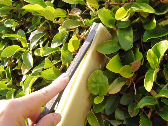
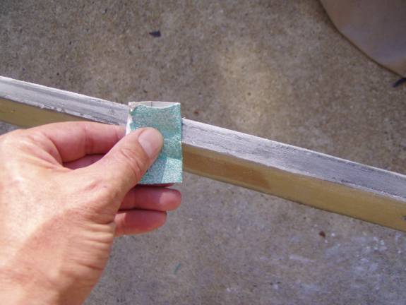
When both front and back sides of the spar are fully cured, carefully trim the fiberglass to the edge of the foam with no overhang.
Spars after fiberglass BID shearwebs have cured
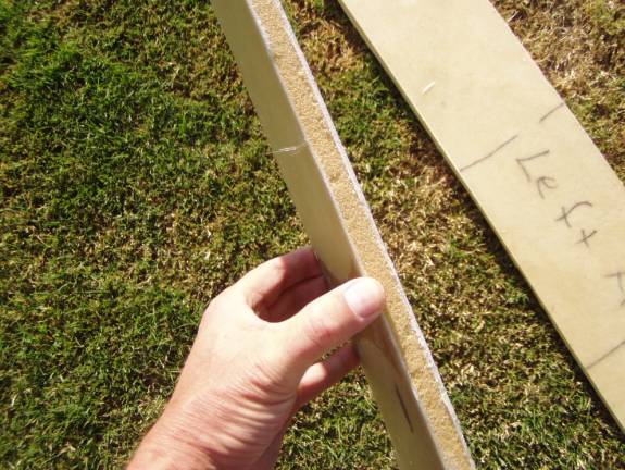
Notice inboard thickness of 6 layers of glass
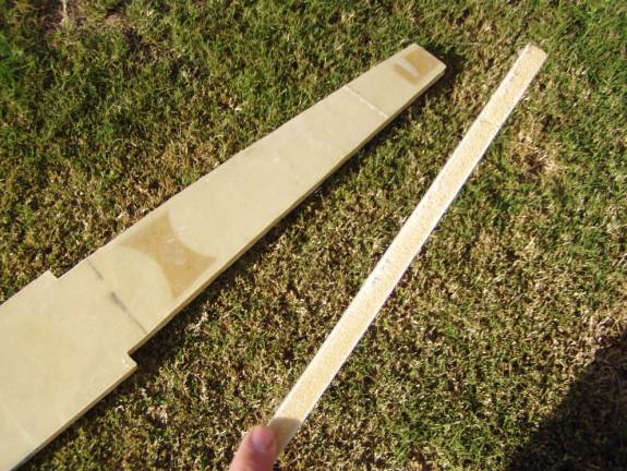
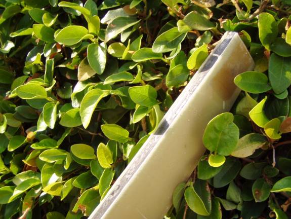
Outboard edge with its two layers of glass
Now it is time to build the sparcaps. They are the same for the top and bottom of the outboard spar and all four will be made the same way (two for each outboard spar). The spar caps are thickest at the inboard edge, the edge against the phenolic.
From your spool of Graphlite, cut the following lengths:
4 ea. 30 inches,
4 ea. 40 inches,
4 each 60 inches,
4 each 74 inches
Lightly scuff the Graphlite by running it through your hands with 100 grit sand paper. Remember to use gloves and a dust mask, you don't want to breath the carbon dust. Use acetone on a rag to clean the surface and remove any sanding dust.
Spread a drop cloth on your work table or on the floor.
Stack 1 each of the four lengths of Graphlite rectangle together with them all biased towards one end. Lay the stack on your drop cloth with the longest legth on the bottom and the shortest on top and the others in order. Prop up the two ends with a 1 inch thick block. Notice that the stack forms a slight curve. Once you have a set up that you are happy with, use our laminating epoxy to coat each side of the Graphlite rods and bond the group together into a single unit. When cured, use your 100 grit sandpaper to roughen all sides of the resulting spar cap. Build a total of 4 spar caps.
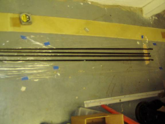
Outboard Spar Caps Curing – notice 1” block
at ends
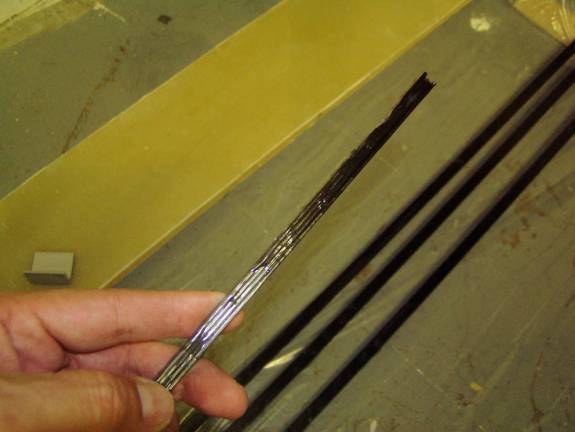
Inboard edge view of outboard spar caps – 4
layers thick
Outboard Spar Cap position
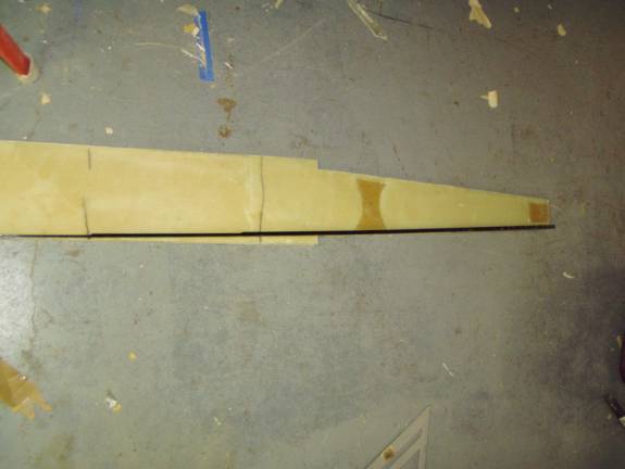
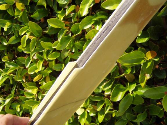
Remove about 3/8” of foam from both top and bottom edges of the spar. Where the step occurs, dig the foam out deeper to smoothly transition from about 18” outboard from the step to just inboard of the step. Refer to the two Detail A and Detail B drawings for an indication of the approximate location of this slot.
Remove foam down to phenolic blocks
Foam removed smoothly through step
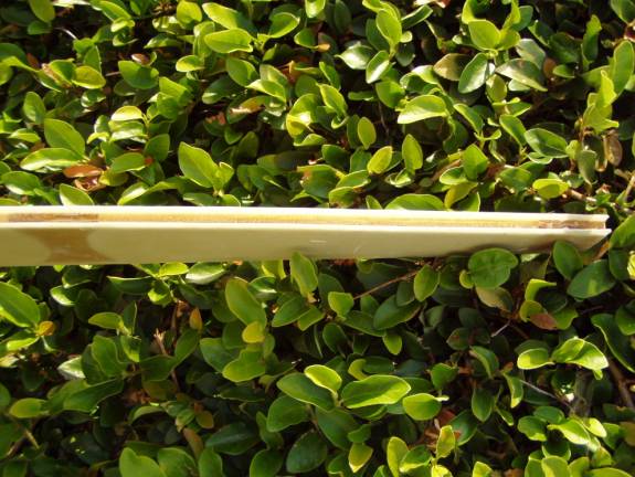
Trial fit the cured spar caps into the slots to insure they are the correct depth. The thicker end of the spar cap is toward the phenolic end of the spar. We want to use as little epoxy matrix as we can, yet completely encapsulate the spar caps in the slots.
Test Fit spar cap
Spar Cap test fit
Spar Cap test fit through step
Mix up a thick flox mixture and fill about ½ of the slots in the top and bottom. Smooth this mixture to completely cover the foam core. Now mix up a batch of straight resin. Laydown about an 1/8" of pure epoxy on top of the flox down the entire length of the slot. Work this with a stick to make a soupy flox layer on top and wet the fiberglass sides where they will contact the spar cap.
Install the sparcaps into this flox mixture. Place the thick end of the sparcap towards the inboard side, the side with the phenolic blocks. Insure the spar caps are below the level of the exposed shear webs. Work the spar cap in and out, back and forth to force all trapped air out of the joint. Epoxxy should ooze out and cover the top of the spar cap. If this does not happen, pour epoxy over the top of the spar cap and make sure there are no gaps between the cap and the side of the shear web. Reveiw the photos down abit showing the spar cap after the epoxy has cured; there are not air gaps and the epoxy/flox can be seen to ooze out of the joint and collect on the top of the spar cap. don't skimp on resin here. Let it dribble everywhere, we will clean up the side of the spar caps with a rag and acetone once we are happy that we have worked out all air.
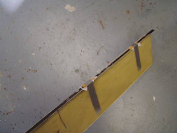
Securing Spar Cap while epoxy cures
I uused small wooden blocks secured with duct tape to hole the spar caps in position while the epoxy cured. Strips of peel ply insured the wooden blocks did not bond to the spar caps.
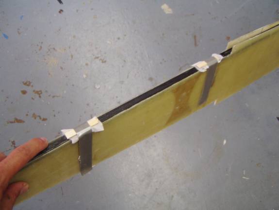
Method to secure cap for epoxy cure
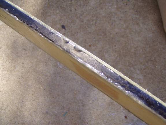
Flox has oozed to seal spar cap
notice in these pictures that the epoxy and flox oozed out to fill all voids between the spar caps and the shear webs.
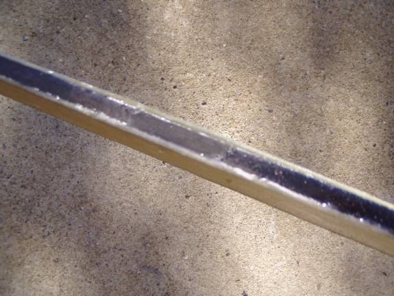
Another view of epoxied spar cap
Make sure the spar cap is solidly epoxied
Once cured sand sparcap – no gloss allowed
Sand a small radius along both sides of the spar caps.
Apply a two bid layup over the top and bottom spar caps extending at least 1 inch down the sides.
Remove a ¼” of foam from the outboard edge of the spar and fill with a flox mixture.
Add two more layers of BID, 3" wide across each of the phenolic and around the sparcaps. Let cure.
Clear the two holes in the phenolic. After the main spar is built, the main spar and the outboard spars will be clamped together and the holes will be drilled all the way through. They will then be reamed and the bushings will be installed.
Set up your curing oven and post cure the two outboard spar caps. Congratulations, the wing building has begun.