Chapter 7 - The Wing
Section 4 - Wing Internals
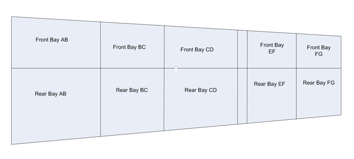
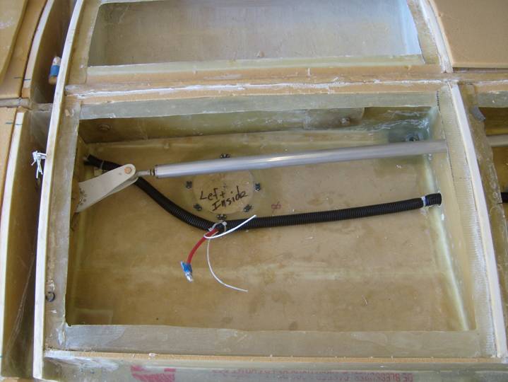
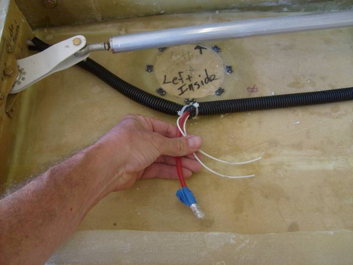
Bay by Bay Review --- Wing Bays located behind the spar.
Before we close the wing let us review each wing bay to insure we are ready. The wing bays are described by the ribs that bound them and whether they are forward of the spar or back.
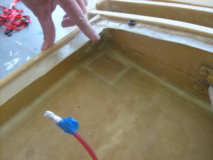
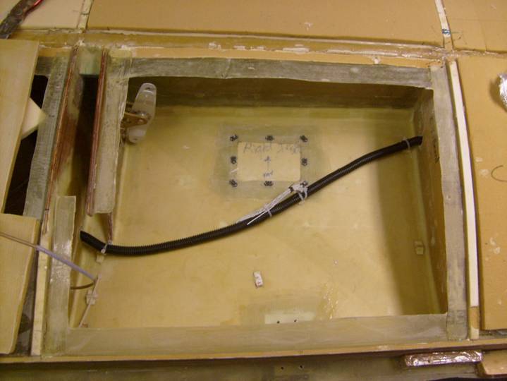
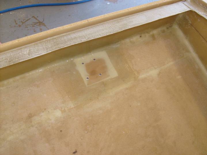
The photo below depicts the Rear FG bay. This is an empty bay. All bays (except the fuel bays) need to have holes drilled through the rib to allow for air pressure equalization. A single .5" hole is fine. Dig out the foam an 1/8" back from the hole and fill with micro. I find the easiest way is to just fill the hole, then come back after cure and redrill to 3/8". The bays that have wires going through them do not need extra air holes as the hole that passes the wire is sufficient. Trim the flanges so there is about 1 inch bonding surface. clean out the bay, giving it a good sanding, and vacuum.
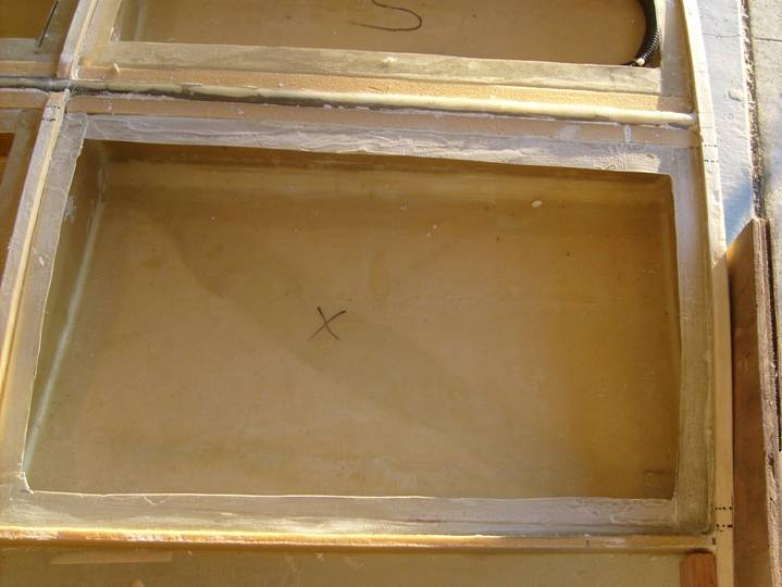
Rear FG bay
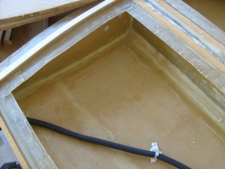
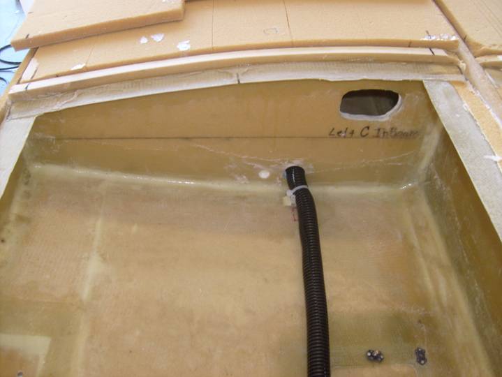
The following photo is the Rear EF bay. This bay is also empty. Prepare the flanges by sanding them to remove all gloss. Insure you have air holes in this bay.
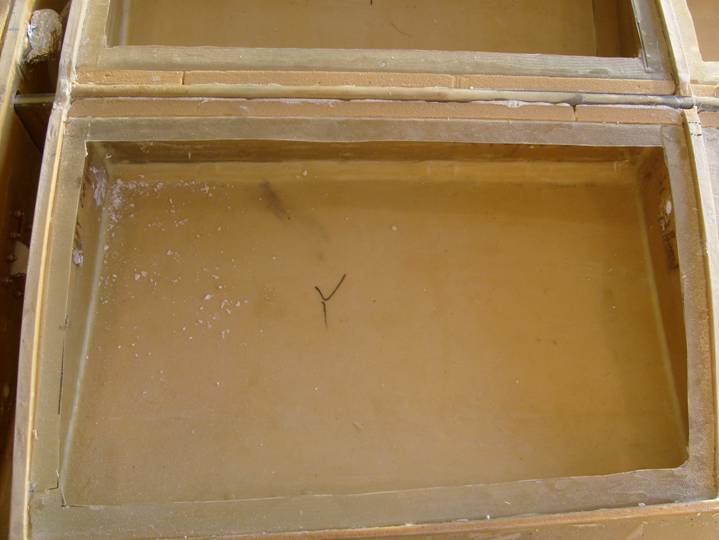
Rear EF bay
Rear EF bay
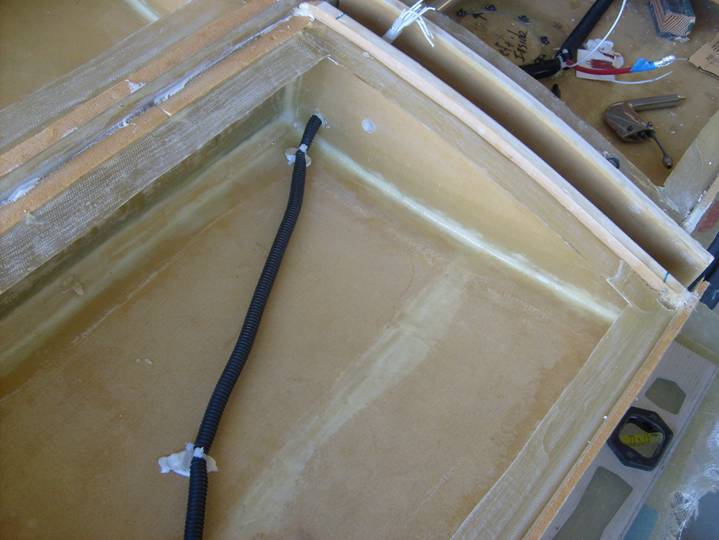
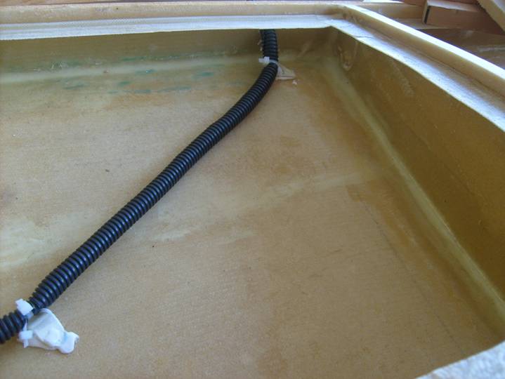
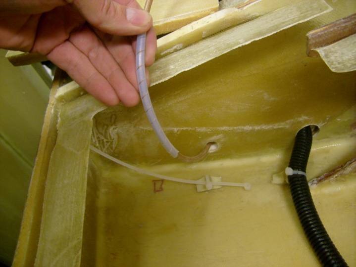
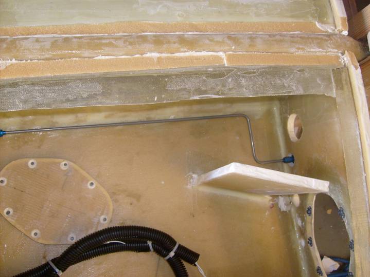
The rear EF bay on the pilot side has a wire bundle routed to and through the rear spar for the aileron trim tab. See below.
Rear EF bay Pilot side
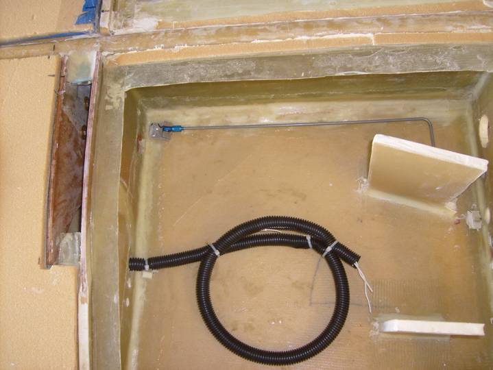
Below is another shot of the aileron trim wiring routed through the EF bay to the rear spar. Notice the correct way to tie a wire bundle to the fiberglass skin, using two twist ties.
Rear DE Bay Pilot Side
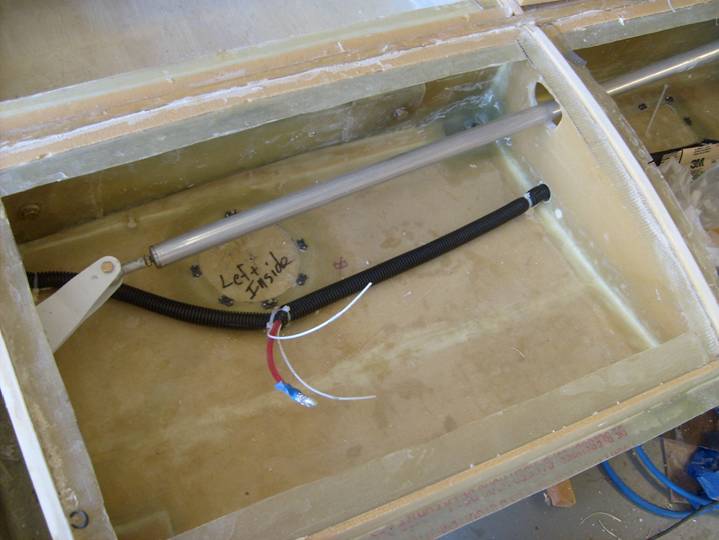
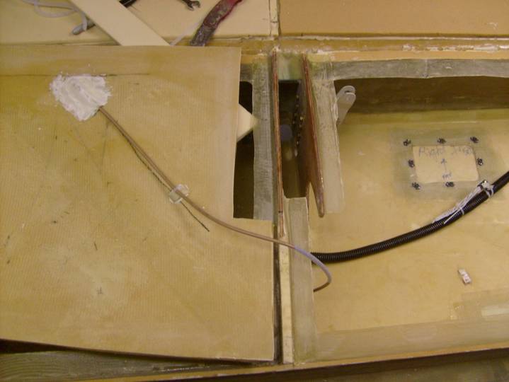
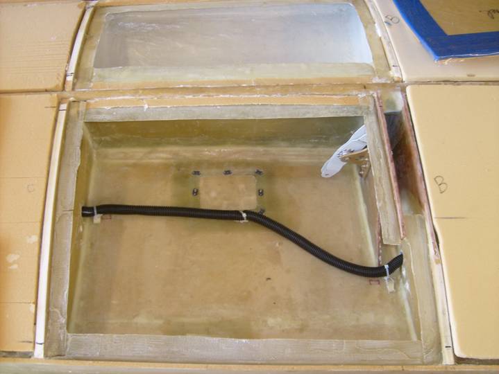
The following photo is the Back DE bay, this is not really a bay as it is the space between the inboard and outboard wing sections. This space will house the aileron pushrod running from the aileron bellcrank to the aileron. Also the wire bundle for the wing tip lighting pass through this space, under the spar where a connector allow this wiring to be uncoupled to remove the wing tip. Inspect the flanges, the quality of the nut plate installation, and the overall tidiness. This space will be accessible when the outboard wing is removed.
Back DE Bay
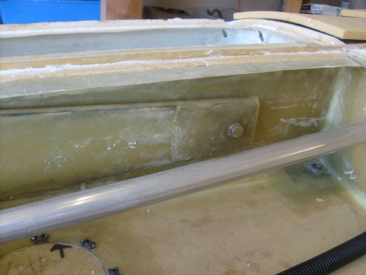
The following photos are of the rear CD bay. The next couple of pictures emphasize the clearance of the aileron push tube to the C rib through its entire motion range. There is an extra half inch or so to allow for wing flexture when you are pulling those high G maneuvers.
Back DE Bay
i
Back CD Bay
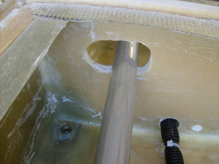
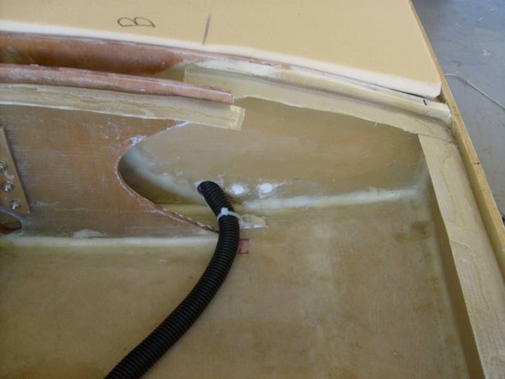
The following picture of the CD Bay shows the access panel that the pitot tube will be mounted to. The wires for the pitot heat and the pitot tube itself are strain reliefed right at the panel. This is done on the trailing edge side of the wing so that the wiring bundle is not in the way when attaching the wing tip. This is done through the access panel and is easier than it looks.
Rear CD Bay
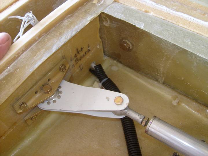
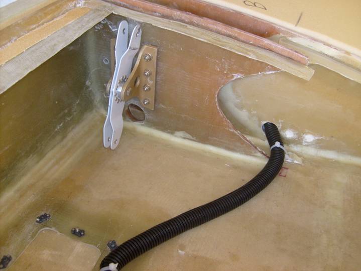
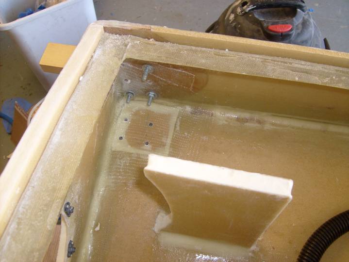
Now is the best time to securely bolt the aileron bell crank in place. Use torque watch on the bolts so you remind your self this has been done and inspected. Insure the bellcrank moves freely and does not bind or interfer with the wiring bundle passing near by. Insure the wiring bundle can not come loose or flop around to interfere with the aileron control system later.
Below is the proper positioning of the pitot tube and wires. Wrap the end of the tube in tape to prevent fod from entering the system.
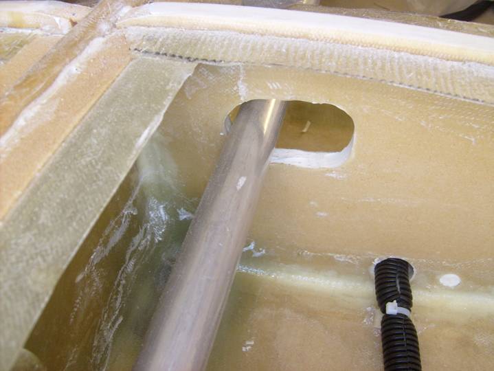
Inspect the outboard flap attach point. Sand the glass so there are no sharp edges, remember you will be attaching the flap hinges later and you will be working in a blnid hole; you don't want any sharp surprises waiting for you.
The wing tie down point is in this bay. Run a bolt through the nut plate to unsure there is no resin that will jam it up later.
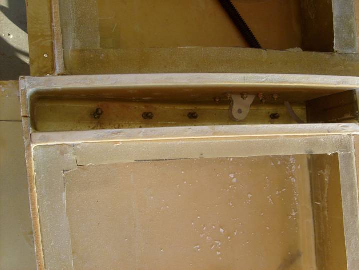
The outboard spar attachments are in this bay. Each of the bolts may be different lengths. Mark these on the outboard spar in sharpie for future reference.
Below is another view of the outboard spar mounting.
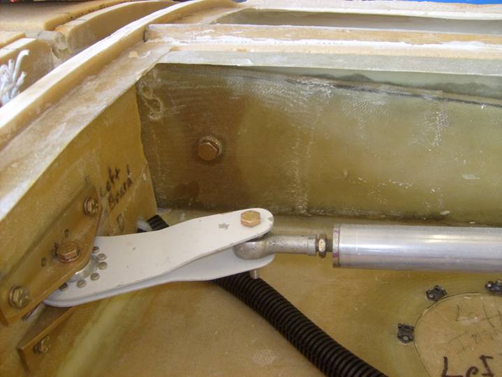
Rear CD Bay with Outboard Spar Attachment
The following photo shows the Rear BC bay. There is a lot going on in this bay. A wiring bundle passes through this bay and must meet the criteria laid out earlier in this section and in the wiring section. On one side of the wing there are extra wires for the addition of an optional roll servo.. If these wires are not used initially, they need to be securely tied off as shown in the photo below. the aileron pushrods should be installed one last time to insure they do not interfere with either the top of bottom wing skins or the wing ribs. The Rear BC Bay is also where the antenna cable connects to the copper foil nav antenna in the wing. (I wonder how much longer folks will be installing Nav antennas.) The antenna cable needs to be insulated from the wing rib as do all the other wiring and needs to be attached to the bottom wing skin where it exits the wing rib and then the top wing skin where it exits through a hole in the skin. this wire will be dressed later when the wing is sanded to shape. The antenna cable is secured at its exit with micro as shown in the photo a couple down. This bay will be accessible through the access panel, but it is tight. The top wing skin for this bay has a jog in it around the BB ribs securing the landing gear. The small remaining space will be filled in with a strip of foam later.
Rear CD bay
The following shows detail of the top skin for the Rear BC bay with the NAV antenna cable
Rear BC bay with the NAV antenna cable
Detail of the protective sleeve on the NAV antenna cable where is passes through the B rib. No glass contact is allowed on cables or wires. this wrap will be pushed through the rib hole and secured on each side of the rib with zip ties.
Protective sleeve on the NAV antenna cable
Below is the middle flap attach reinforcement, again insure there are no sharp edges to cut you later.
Secure the aileron idler and put torque watch on the nuts.
Properly Dressed Wire Bundle
Properly Dressed Wire Bundle
Rear BC Bay
The following photos are of the rear AB bay. This bay has the wing walk reinforcing stands and the brake line as well as the wire bundle. Notice that the wire bundle is tied off and secured inside the wing bay, this is done to store the wires out of the way until the wing is attached to the fuselage. Compare the flanges in the preceding photo with the flanges in the following photo. Notice that the following photo has glossy spots on the flanges. These areas all need to be sanded so there is no gloss.
Rear AB bay with brake line
Temporarily secure Wiring Bundle
Inspect the inboard flap reinforcing plates and all nut plates for the access panel. This is a good shot of the wing walk reinforing stands. Notice how the rear one is curved to allow access to the inboard flap attachments.
Rear AB Bay
Prepare all of the flanges and give all of the bays a sanding to remove any sharp edges. Wipe the bays down and vacuum them out.