Chapter 7 - The Wing
Section 4 - Wing Internals
Fuel Proofing Tanks
It is difficult to over emphasize the importance of properly fuel proofing the fuel tank. A leak is difficult to fix later, so it is better to do an extra good job fuel proofing even if it costs a bit more, takes a bit longer or adds a bit of weight. The job is done in three steps: 1.) structurally sealing the tanks, vinyl ester sealing the tanks, and finally coating the tank with a tank sealant.
Structurally sealing the tanks involves preping all tank surfaces and closing all gaps where fuel or air could possibly escape. Points of particular interest are the areas under the top flanges, around the slosh gates, and around the air vent tube. If a hole is found larger than a pin, fill it with micro and cover with a layer of fiberglass. Next sand the tanks smooth. This is important becasue we need smooth surfaces and smooth transitions between the tank walls to insure a good surface for the next steps. Wipe with acetone to clean the surface. Finally fill the fuel exit port and the fuel drain port with softened bees wax.
The second step is to fill all of the micro-holes including pin holes in the surface of the tanks. The tanks should be finished from the previous step and sanded with a 180 grit sand paper to remove all gloss from the surfaces. Vinyl ester resin is then painted onto the surface. Do this in small batches as it is best to mix it on the hot side (more activator) about .8 drops activator per gram of resin. I like to use a pigmentation agent in the resin to make it easier to watch the coverage. Let this cure completely, it may take several days, you do not want it to gum up your sand paper. Then use a 180 grit sandpaper to sand most of it off, again resulting in an even no-gloss surface. This process is repeated at least four times to completly gaurantee all pin holes are filled. If you sand off most of the material you are not adding much weight. B ecareful not to get any vinly ester on the top surface of the flanges. We want an epoxy to epoxy bond up there.
Finishing Fuel Bays
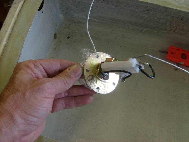
Components required for fuel gauge
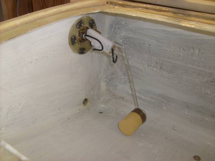
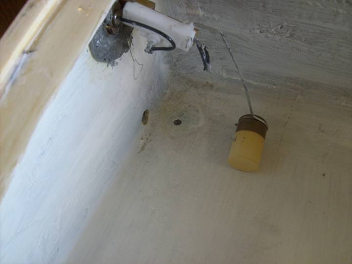
Test fit the fuel gauge sender. The ring fabricated earlier will be used to bond to the inside of the fuel bay. Use a setup similar to the following picture get the sender functioning. We need to bend the wire in such a manner that we get full range on the gauge as the arm swings from the top of the tank to the bottom. Below is a diagram of the shape of the sender wire I ended up using. You have the choice here of how you want to offset your fuel scale. You can have it read true, or you can offset it a bit where the gauge reads full when the tank is, say 85% full. This gives you a somewhat expanded scale at the lower gauge reading.
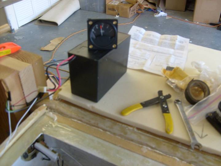
Test Setup to calibrate Sender
It is now time to bond the fuel sending unit nut ring into the inside of the fuel bay. Use 120 grit sand paper to degloss the area of the fuel bay where the ring will be bonded, and the outside of the nut ring. Clean surfaces with acetone. Apply a layer of packing tape to the fuel sender as a release agent as shown below. Use bees wax to coat the screws that will be used to secure the assembly while the epoxy cures.
Tape on fuel sender as release agent
Fuel sender ready to bond into place
Test fit one last time to insure everything works properly, that you didn’t get the right and left sender switched and that the nut ring fits flat against the inside of the tank.
Create a think mixture of epoxy, flox and a bit of cabosil. The cabosil allows the mixture to be a bit wet without being runny. Apply this to both surfaces and press the fuel sender into place, removing excess epoxy/flox as you go. Be careful not to get any on the fuel sender mechanism.
Let cure.
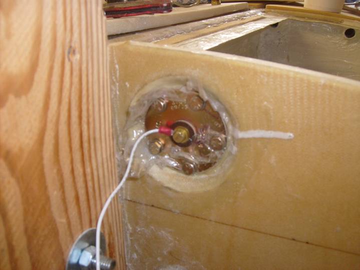
Fuel sender nut ring bonded in place
Remove the fuel sender unit and inspect the nut plate. Once satisfied reinstall with final hardware using a washer under the AN3 bolts. Use Proseal on the sender plate and on the nutplate to completely seal the unit.
Proseal applied to the fuel sender
The slosh gates are installed in a very similar manner. It is important to install them on the correct side of the ribs, the inboard side. We want fuel to flow easily toward the fuel outlet and not run toward the tip in a steep bank.
Lightly roughen up the surfaces to be bonded. Test fit and adjust if necessary to insure smooth and proper operation. There should be about 3/16” opening at the bottom of the slosh gate to insure proper fuel flow in case the gate gets stuck at some point. This will allow enough fuel to continue to flow.
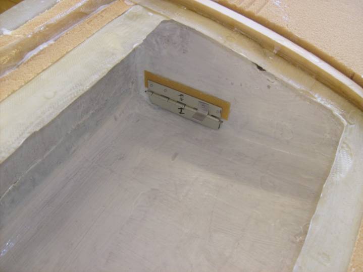
Installed slosh gate
Use the same epoxy flox mixture as before to bond the slogh gate to the rib. Hole in place with tape while it cures. Insure proper movement of the gate and insure not epoxy finds its way into the hinges.
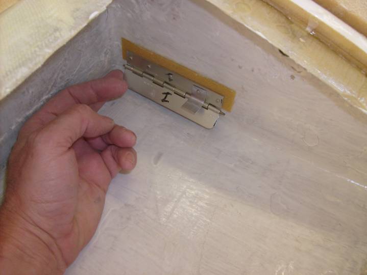
Gate swings freely
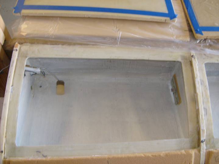
Completed fuel bay ready for closure
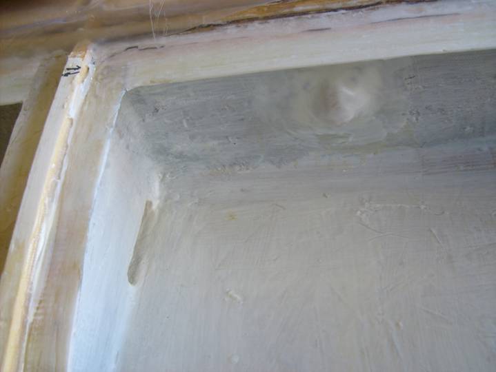
Inspect tank one last time.
Finally, a tank sealant may be painted onto the surface. this step is optional and really depends on how well you feel you sealed the tank on the proceeding step.
Complete.