Chapter 7 - The Wing
Section 4 - Wing Internals
Wiring the wing
The Super2 wing is designed to be built independently from the fuselage and to be removable. As a part of this, all connections to the wing: fuel, brake lines and electrical are terminated in connections at the wing root/fuselage interface. The wiring is no different and we use MOLEX style connectors to make this connection. The functions that need to be wired in the wing are as follows:
Right Wing
- Strobe Light
- Nav Light
- Roll Trim Servo
- NAV antenna
Left Wing
- Strobe Light
- Nav Light
- Pitot Heat
Strobe Wiring
The wiring for the strobe described here supports the older style ‘flash tube’ type strobe as well as the newer LED style. The older style requires thicker wire and fewer runs. In the following discussion the old style is referred to as the Strobe wiring and the LED is supported by the wiring described as additional for expansion. If you use the older ‘flash’ style then just use the 3 Strobe light wires, and if you use the LED type you will also need to use the 4th ‘strobe expansion’ wire. I ran all wires so I could upgrade in the future or allow for changing my mind later.
The strobe wires are noise generators so should be routed separately from the autopilot wires. The other wires in the wing, the nav and pitot heat don’t care and can be bundled with the strobe wires. The NAV antenna, of course, is a special case and will be routed far from any other wire.
The Strobe and NAV wires run from the wing root to the wing tip, so require intermediate connectors where the outboard and inboard wing met.
The three wires for the older style strobe should be 16 gauges and the additional wire for strobe expansion should be 20 gauges. If you know you are going to use an LED system, you can run 4 20 gauge wires. Check your Strobe manufacturer’s recommendation on wire gauge.
The length of wire that I used for the strobe was 103” for the inboard section and 68” for the outboard section. Molex connectors were used at the wing root and at the joint between the two wing sections. I bundled the strobe and nav into a single 9 pin connector.
NAV Wiring
The same is true of the NAV lights, the old bulb style NAV lights only required two wires, but the newer LED style uses 4. This is why you will see NAV wires and NAV expansion wires.
There are two wires for the older style NAV lights that use a bulb and should be 14 gauges and the additional two wires wire for NAV expansion should be 20 gauges. If you know you are going to use an LED system, you can run 4 20 gauge wires. Check your NAV manufacturer’s recommendation.
The length of wire that I used for the NAV wire was 103” for the inboard section and 68” for the outboard section. Molex connectors were used at the wing root and at the joint between the two wing sections. I bundled the strobe and nav into a single 9 pin connector.
Pitot Heat
The pitot heat wiring is pretty heavy duty and requires 14 gauge. There are two wires that run from the wing root to the round access panel on the left wing. This is the access panel between the C and D rib. The pitot is mounted in this access panel.
Autopilot
The autopilot roll servo is mounted on the access panel in the right wing. It is best to route this cable by itself and be sure to check the manufacturer of roll servo you use. I plan to use the TRUTRACK/DYNON/Advance Flight Systems style roll servos. These use a 9 pin D-sub connector and 8 wires. I went ahead and ran 9 wires and twisted the two together required by DYNON. The other types of servos do not care if these are twisted. This cable is run from the root out to the access panel between the B and C rib.
NAV Antenna
The Nav Antenna is installed in the right wing in a manner similar to the comm. Antenna in the vertical stab. The antenna wire is routed at least a foot from all the other wires in the wing. We use a female BNC connector at the wing root so it is easy to connect a standard male BNC terminated coax cable running to the radio in the fuselage. I like to use RG400 for comm, nav and GPS antennas, but will use RG58 for ELT and glideslope.
The first step is to purchase and cut the wires to length as stated above, and then we will label each wire. We will then make bond on wire ties, drill holes in the wing ribs to allow the wires to pass through, bond on the ties, bundle and run the wires.
Let us get started with the cutting and labeling:
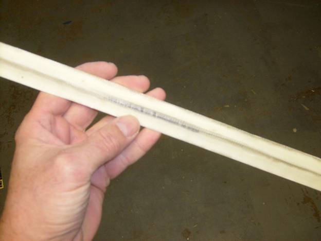
The method I use to label wire is simple, inexpensive and looks pretty good. Below is a photo of the required equipment. The signal names are printed on a sheet of typing paper using a standard Times New Roman font size 9. Clear heat shrink tubing in 3/32” and 1/8” is used to hold the label to the wire end.
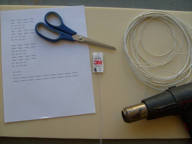
Required tools to label wire
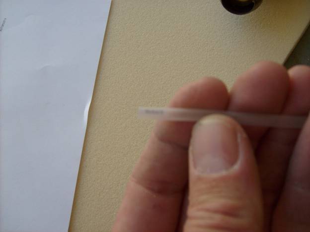
First trim the label so that it will slip into the heatshrink tubing. The 3/32 heat shrink is used for smaller wire like 20 gaugle and the 1/8” tubing is used for the larger wire like 14 and 16 gauge. The photo below is pretty fuzzy but you can see the label inside the tubing.
Slide Label into Heatshrink Tubing
Next, cut the tubing to length and slide over the end of the wire. Finally using a heat gun, shrink the tubing to size.
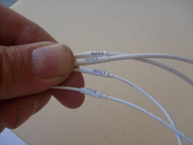
Finished Wire Labels
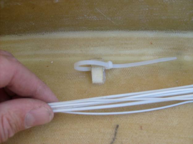
Next we will make bond on wire ties. I have had bad luck with other type of wire ties, especdially the plastic ones with two sided tape. They always pull off. To make our own bond on wire ties take a length of 2 layer precured fiberglass about an inch wide and 18: long. Lay a length of 1/8” (inside diameter) vynle tubing down the center and tape it into place with duct tape.
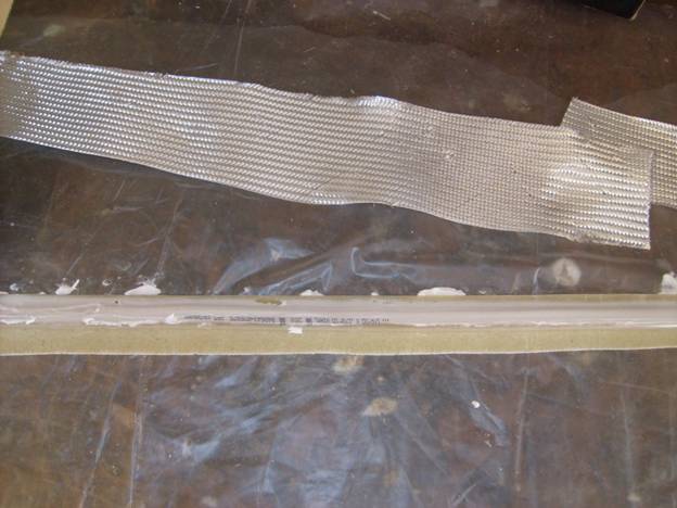
Making bond on wire ties
Use thick micro to fill in between the vinyl tubing and the procured laminate. Finally lay a strip of BID over the top and smooth it along the length of the tubing. Let cure
Finished stip of Bond on Ties – Just cut off sections
Finally use a hack saw to cut off sections about 3/8” wide. Use a thick micro or flox to bond these on to fiberglass surfaces to hold your wires.
Bond on wire tie in action
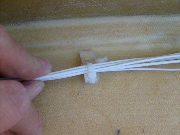
When holding wire down with a bond on wire tie, use the twin zip tie method. One wire tie is looped through the wire tie, then a second zip tie is used to loop around the wire and through the first zip tie. This way the wires are not in contact with the abrasive fiberglass tie.
Twin zip tie to hold wire in place.
Note that the series of photos is intended to show the twin zip tie method. All wires that come near fiberglass should be protected in a sleeve as fiberglass is very abrasive and with vibration of the structure, the wire Can wear through over time. We will discuss how to protect the wire next.
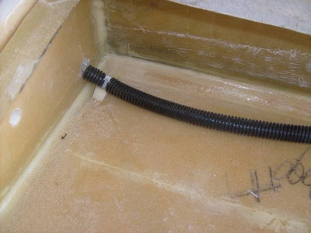
The most important place to protect the wire is where it passes through holes in the ribs. Here we use a wrap around wire sleeve as shown below.
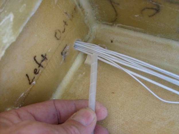
Sleeving to protect wire when it could contact fiberglass.
The split sleeve shown below is good for longer runs as it is light and easy to use.
Sleeving is used to protect wires
As the wire bundle goes through the wing ribs, use bond on wire ties on both sides of the rib and in the center of the wing bay.
In the photo above a smaller hole was used to pass the wires through and two types of sleeve were used. In the following photo the hole in the wing rib is larger and the split sleeve is just run through the rib. This method is a little cleaner and easier.
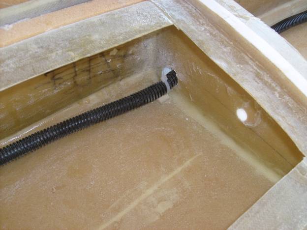
More Sleeving
OK, now we have all the techniques down to run the wires through our wings. Lets make the wires bundles first. You should, of course, use the wire gauges suggested by your manufacturers of equipment.
I ran my wires through the ribs about 3” back from the spar. Use a twist tie near the access panels so the wires do not block your access. Give yourself plenty of extra wires at each end to work with later when you actually install the roll servo or pitot tube.
Good Job.
Complete