Chapter 7 - The Wing
Section 4 - Wing Internals
Wing Hydraulics
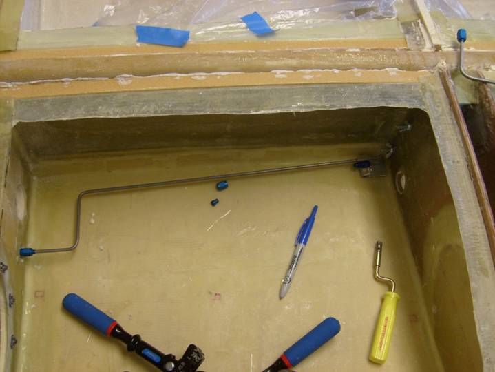
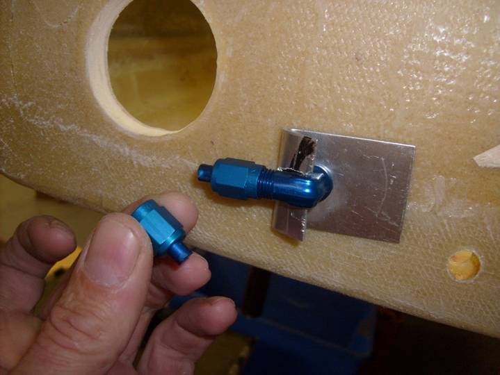
The Super2 uses aluminum tubing for fuel lines and brake lines. The brake line is located inside the aft A-B wing bay. The most important point to be recognized is that the brake line must clear the aileron push/pull tube that passes through this bay. Look at the last photo on this page and note the location of the fitting mounting on the inside wing root. The 90 degree bulkhead fitting points forward so the line can run under the spar and aileron control tube. It is placed about three inches back from the aileron control tube opening and as close to the floor of the bay as practical. The other fitting is even with the gear leg and is located about three inches inbound of the B rib. Mark these locations by drilling a pilot hole through the A rib and the bottom skin. The using a hole saw, cut a 1” diameter hole in the bottom of the wing skin, but not all the way through the wing, leaving the inside bay skin intact. Remove the foam and micro the edges so you have a nice 1” diameter recessed pocket for the bulkhead fitting. Do the same on the inside of the A rib. Make a 1” pocket in the inside of the A rib with the hole saw. Drill the pilot hole so the bulkhead fitting can fit through. The nut will be mounted in the pocket holding the bulkhead fitting in place. Now fabricate two aluminum bulkhead fitting brackets as shown in the photos below. The bracket is a 3” X 1” piece of 1/16” aluminum with a hole at one end for the fitting to mount through, and then a slot is cut in the other end that just fits over the fitting. It is bent up and around the fitting. The purpose of this bracket is to prevent the bulkhead fitting spinning when we tighten nut and the aluminum tubing coupler. This is much easier because the fitting is blind and hard to get a wrench on later when we attach the line to the brake.
Install the bulkhead fitting first with the one on the A rib pointing forward and a bit below the aileron push/pull tube. The one located next to the B rib will point inboard. Two 1/8” rivets through the bracket and through the one layer of fiberglass hold them in place.
Good, now it is time to fabricate our brake lines. First collect the required tools:
- Tubing Cutter
- Tubing Bender
- Flaring Tool
- Deburring Tool
- Marker
- Wire Coat Hanger
- Compressed Air
- Denatured Alcohol
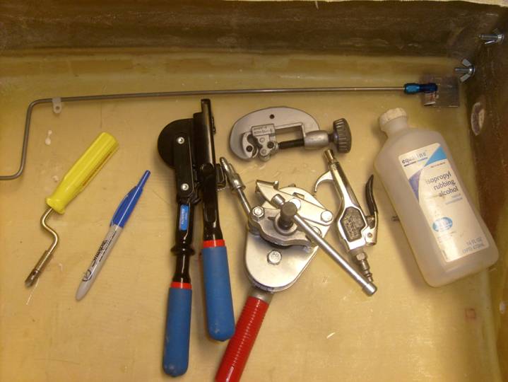
Tools to Fabricate 1st Class Hydraulic and Fuel lines
Next we need to collect the raw materials for tubing assemblies. Our hydraulic lines will be fabricated from 3/32” .035” aluminum tubing. Use only 6061T6 or 2024T4, do not use 3003 as it is too soft and cannot handle the pressures we will be dealing with. The fittings are -3D. Each side will require a 2 foot section of tubing.
The first skill to be mastered is cutting the tubing with the tubing cutter. Take some extra tube and practice. The two things to keep in mind is to allow enough extra tube to extend beyond the cutters wheels and to take small “bites” as you cut. The cutter wheel should spin easily and you should tighten the cutter a little at a time.
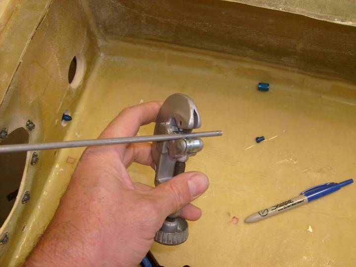
Practice with the Tubing Cutter
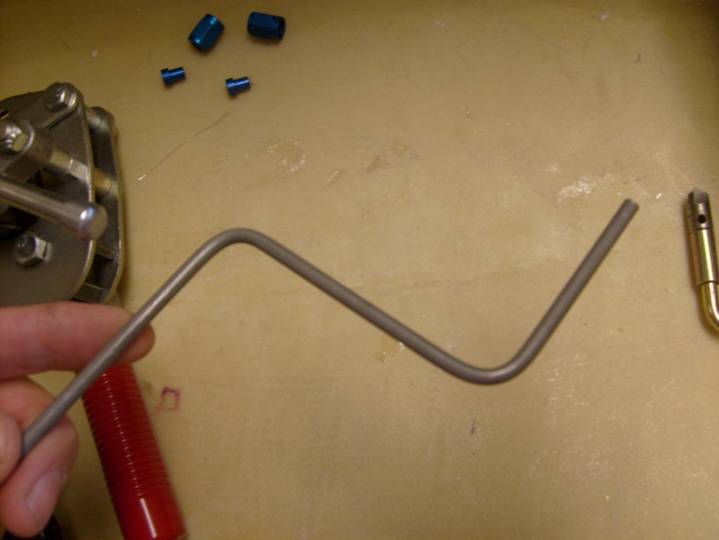
The two bends required in the brake line
Once the tube is cut cleanly through, use the deburring tool to give yourself a clean end. If you do not have a deburring tool, a small exacto knife can be used, but be careful not to nick the end of the tube. These nicks can turn in to tears when you go to flare the tubing.
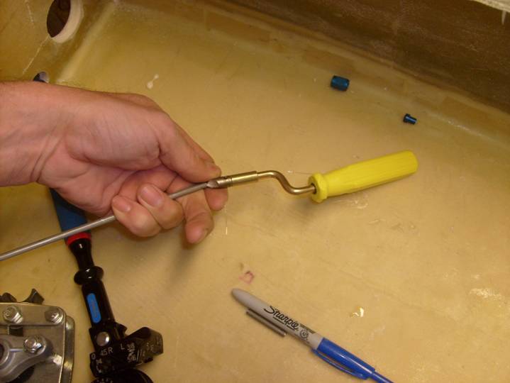
Deburring tool
Once you have a clean end it is time to bend the tubing to the proper shape. I like to use coat hanger wire to model the routing of the tubing, then bend the tube to match. Keep the bends simple and in a single plane as much as possible, the more complex the routing you devise, the more difficult it will be to fabricate. Also remember to leave plenty of straight tubing near the ends of your tube as the flaring tool will need a straight section to grab a hold of.
Next we will create the flare on the end of the tube. Remember to slide the sleeve (AN819-3D) and the coupling nut (AN818-3D) on to the tubing before you flare the end.
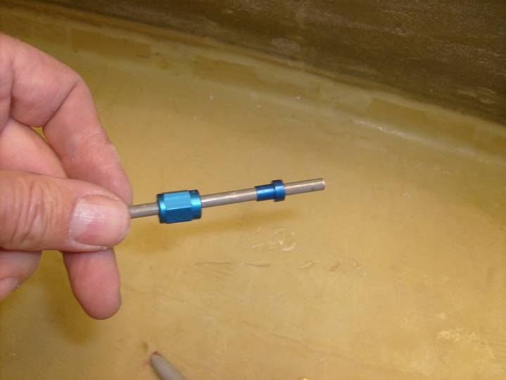
Coupler installed on tube before flaring
Below is a close up of the tubing clamped in the flaring tool, notice that the tubing just slightly extends above the surface of the two clamping jaws. Turn the flaring handle slowly and reverse direction often. Do not over tighten, stop at the first sense of resistance. Again practice, practice, practice.
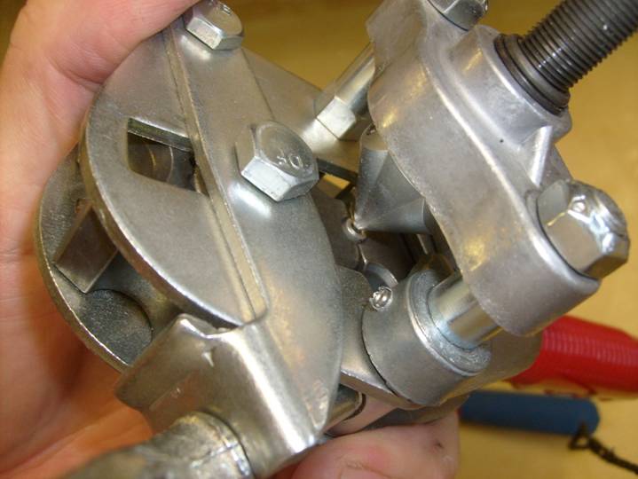
Proper positioning of the tubing in the flaring tool
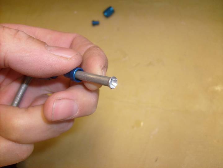
Properly flared end
Above is a properly flared end. Inspect for the beginning of tears as well.

Mark the position of the second Coupling Nut
Finished tubing Length
Finally cut the tube to size. Now remember to slide the coupler nut and end on before you flare the last tube end. You will not be able to get them on after you flare the end of the tube and you will have to scrap the tube if you forget.
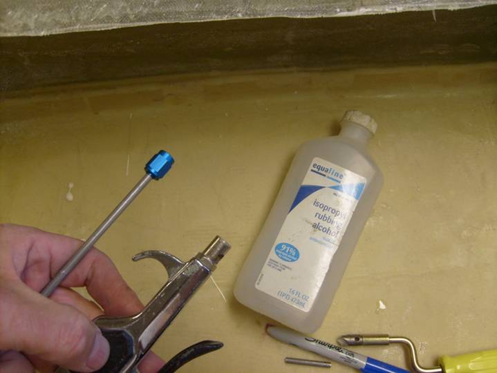
Time to clean out the tube
Use alcohol and pressurized air to flush all debri from the tube.
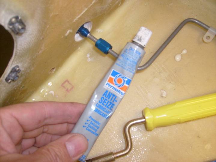
A tiny dab of anti-seize is used on the threads
We use a bit of anit-seize on the threads of the coupling nut, but do not get any on the fitting itself, just the threads.
Cap to seal the system temporarily
Finally use a cap to seal the system for now.
Complete