Chapter 7 - The Wing
Section 4 - Wing Internals
Flap Hinge Installation
In the last section we fabricated the flap hinge components, and in this we will install them on to the wing. First lets review the orientation of the flaps on the Super2.
The flaps run the entire length of the inboard spar section (likewise the ailerons run along the entire length of the outboard wing section). It is important to understand the terms used through out this section. Refer back to the prints that were used to fabricate the aluminum flap hinge components. They will be referred to by name through out this page.
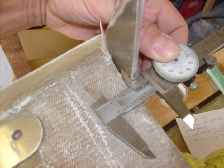
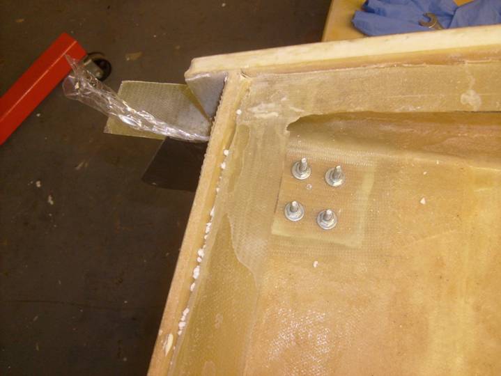
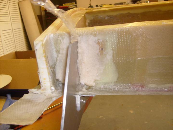
Step 1: trim lower wing skin 1.25” behind the aft side of aft spar on the inboard wing section only. See the following photo to get an idea of the placement of the trim line. Measure from several places along the trailing edge spar, then use a straight edge to insure a straight line for the entire length of the flap edge. It is more important that the line is perfectly straight than it is that the line follow a fixed distance from the spar. USe a cut off wheel to trim away the excess material aft of the line, then use a long sanding block to bring the edge right up to the line.
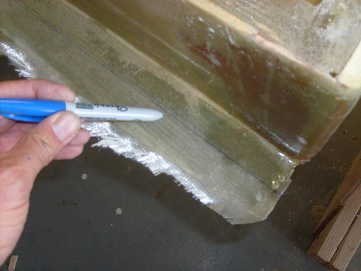
Trim Lower Skin
The Flaps will hinge from a point below and behind the trailing edge of the wing and it is important that the hinge points are absolutely co-linear. This is achieved with the help of a flap jig. Fabricate a flap jig from a 74" length of stiff stock. I used a piece of 1.5" X 1.5" X 1/8" angle iron I cut from an old bed frame.
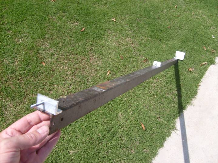
Finished Flap Jig
Create three precision angles from aluminum angle. The requirement for these parts is for the three hinge plates to securely attach to the steel flap jig and be able to rotate without the end of the hinge hitting the flag jig. I found that a large piece of aluminum angle worked better than the small ones. Look at the picture above and notice that the angle close to my hand is rather small, and the one at the other end is quite large. The large one worked better in that it held the hinge plane stable. Look through the photos throughout this web page and see how the flap jig is used to better understand its construction. It is easier to build all the aluminum angles at the same time so they a dimensionally equivalent. The precision angles are precision because all of the holes are identical on all three angles and the same distance from the edges of the angles. When attatched to the flap jig the angles will all be squared and aligned to the steel angle iron.
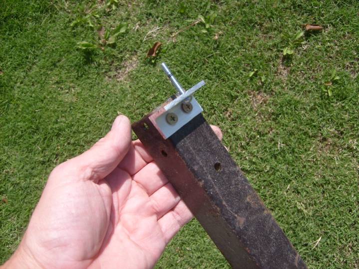
Close up of precision angle
Mount the aluminum angles to the steel flap jig so that the faces of the outside angles are 35.875" inches from the center angle. That is the three angles are equally spaced. Use a carpenter’s square to insure the angles are exactly perpendicular to the face of the angle, so all aluminum angle surfaces where the flaps hinge plates mount, are co-planer. Sight down the mounting holes and insure the holes are collinear. When viewed, the three holes should appear perfectly concentric. Good, now that we have our flap jig we can start drilling mounting holes in the wing for the flap hinges.
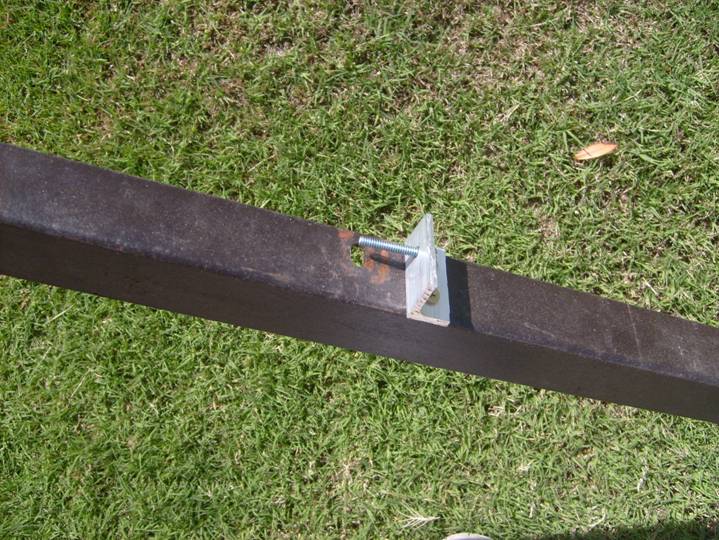
Center Precision Angle
Flap Alignment Jig Angle
We will drill a few holes in the wing strategically placed, then allow the flap assembly jig to position the flap hinges so we can match drill the rest of the holes. The flap plates will not rest perfectly flat against the wing surfaces due to the geometry of the flaps, so we will use a thick flox and epoxy mixture to create a landing pad for each hinge.
There are three degrees of freedom for the flaps. The first is in the inboard/outboard direction. This will determine the position of the flap hinges span wise. The first hole that locates the flap hinges in this inboard/outboard direction is drilled through the aft spar. This hole is precisely placed, souse a straight edge or scrap aluminum plate as shown in the picture below to define the inboard plane of the A rib. Then measure outboard from this plane 1.4” inches and draw a vertical line on the spar.
Vertical Line drawn to place inboard flap
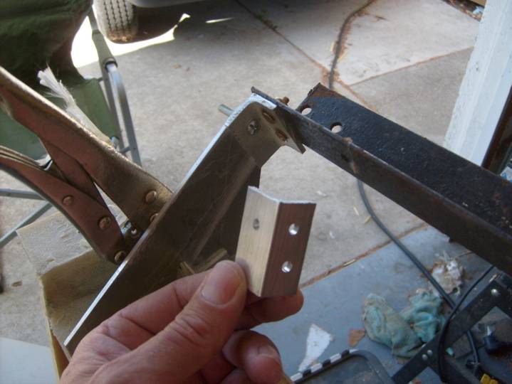
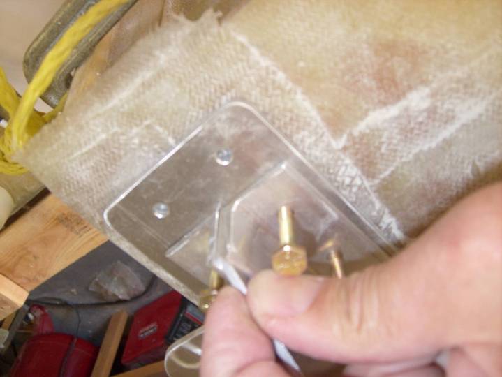
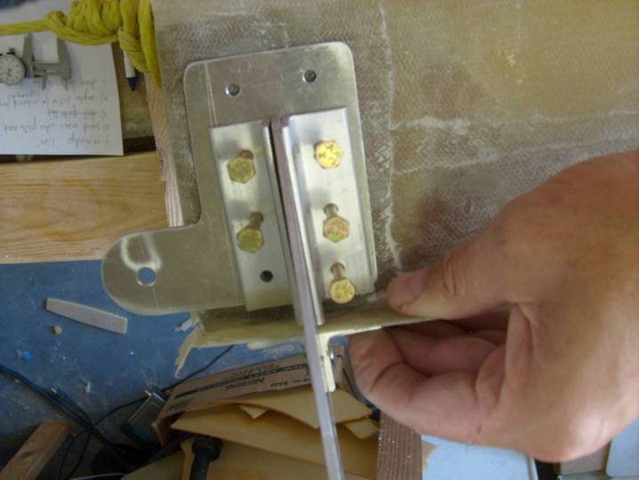
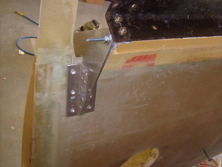
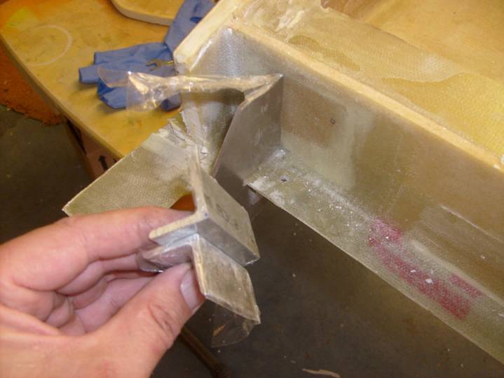
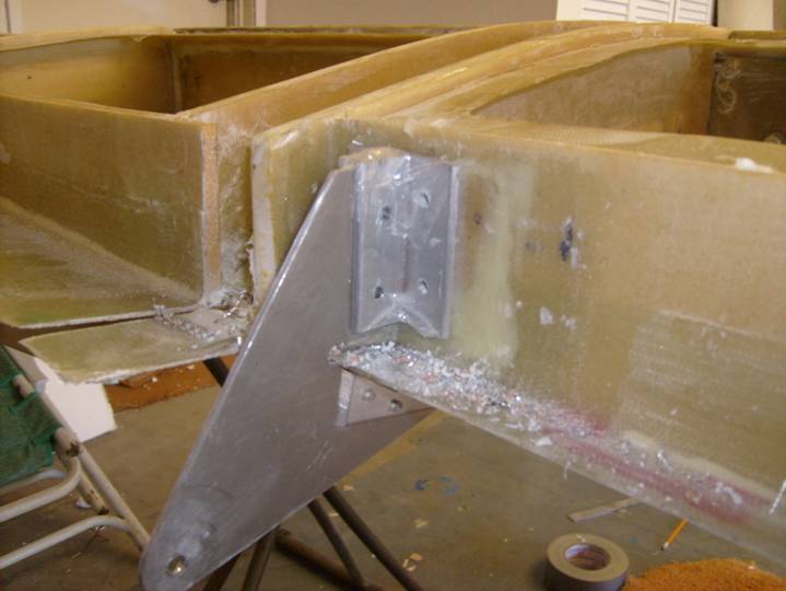
Observe the photo below and notice the inboard flap hinge assembly that consists of the hinge plate, the aft spar plate and two angles that hold them together. We need to prepare the two angles. We are going to match drill the six holes in the aft spar plate into the two support angles first. These are the two aluminum angles seen in the photo above that attach the hinge plate to the aft spar plate. Using the hinge plate as a thickness guide, clamp the angles to it, center the hinge plate between the six holes in the aft spar plate and match drill the holes. Do not drill holes through the angles and through the hinge plate at this time, only through the aft spar plate. This will result in the hinge assembly seen above; it is this assembly that we will mount first to the wing. Notice that a few bolts are loosely holding the assembly in alignment.
The center hinge assemblies do not attach to the rear spar, only the bottom wing skin. The outboard flap hinge assembly does attach to the rear spar as well as the bottom wing skin, but does not have a spar plate as the inboard spar does. Mark all of the parts so they can be returned to the proper assembly and in the proper orientation. For example, mark the aluminum angles as to which side of the wing, which hinge, which side mounts to the hinge plate, which side of the hinge plate and which side is up.
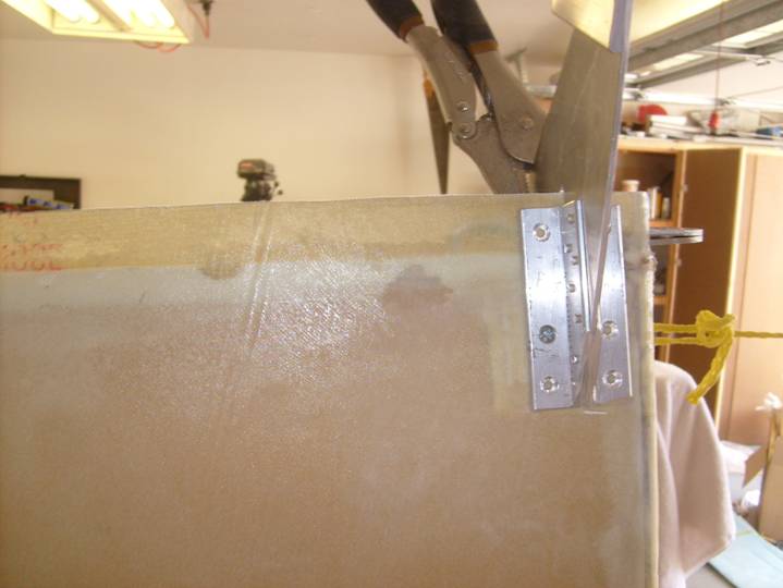
It is now time to bolt the hinge plates to the flap hinge alignment jig. Once this is done, hang the complete assembly on the trailing edge wing skin flange. You will find that the notch cut into each hinge plate is designed to miss this flange, and these can be used to hang the entire assembly as we work to position it.
This is the hole that will be first drilled through the aft spar
Precision location Hole for Aft Inboard Plate
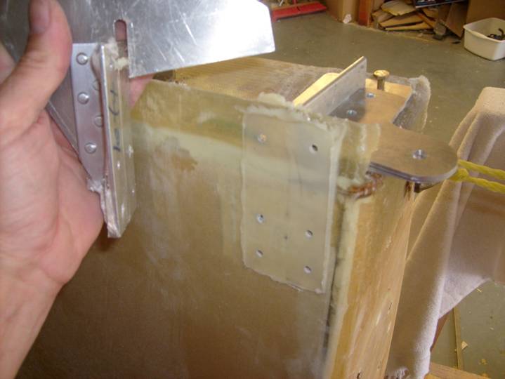
As you did to drill the holes in the flap hinge angles, clamp the entire inboard and outboard hinge assemblies together as shown in the photo below. Remember we have not yet drilled the holes through the angles into the flap hinge plate, only the flap aft spar mounting plate. Lift the hinges attached to the jig up against the bottom skin and rotate all of the hinge plates so the hinges are aligned flat against the bottom skin and flat against the aft spar. Tighten the screws holding the plates against the jig angles. As mentioned before, the bottom hinge plates will not be perfectly flat against the skin, this is OK.
Locate the lower, inboard hole in the inboard flap assembly. It is the hole in the above photo in the flap hinge assembly that does not have a bolt through it. Align this hole in the flap hinge assembly with the line you drew 1.4” inboard of the edge of the A rib, mark the location of this hole.
Drill a 3/16” hole at the intersection. This hole will locate the lower inboard mounting bolt of the aft spar mounting plate of the inboard most hinge flap.
Before we go any further and begin locating the hinges, let’s review the degrees of freedom of the flap hinge and define what will define its location. We will mount the aft spar plate to the inboard aft spar with a single bolt-the one we just drilled. The inboard hinge plate will be clamped to the aft spar plate and angles as shown below. Since the flap hinges are clamped to the alignment jig, this arrangement will define the location of the hinges in the inboard/outboard direction (side to side). The hinges will then be pulled up against the bottom skin to define the hinges location in the up and down direction. Finally the hinges will be mounted up against the aft spar, which will define their position in the fore and aft direction. The jig will force the hinge plates to all be parallel with each other and the hinge mounting holes to be co-axial. Before going any further, be sure you understand what controls the position of each hinge in all directions.
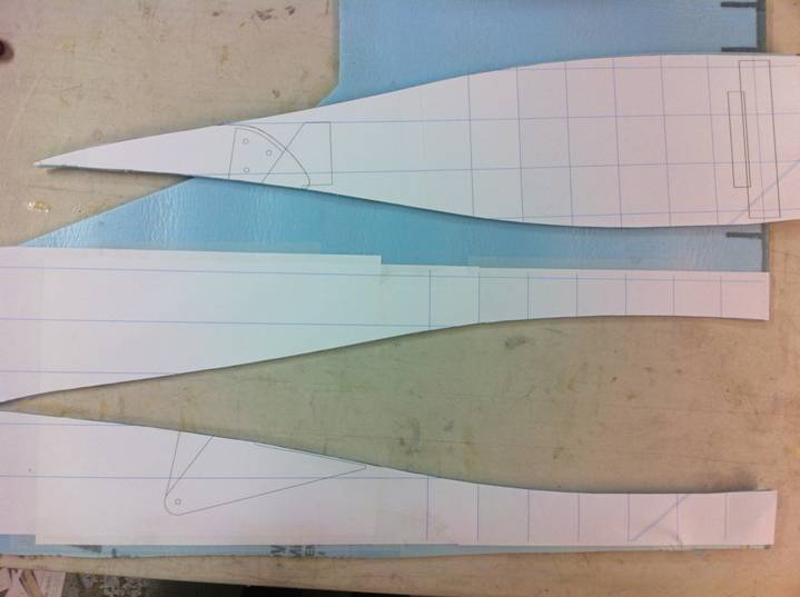
Below are a set of templates that are used to locate the hinge pivot point with respect to the wing bottom. I took a sheet of 1/8" polystyreen foam and glued the templates on them, cutout the wing section. The templates are mounted flat against the hinge plates. These template are also used to position the flap with respect to the flap later on.
- Inboard Flap Hinge Pivot Template 1
- Inboard Flap Hinge Pivot Template 2
- Inboard Flap Hinge Pivot Template 3
- Inboard Flap Hinge Pivot Template 4
- Middle Flap Hinge Pivot Template 1
- Middle Flap Hinge Pivot Template 2
- Middle Flap Hinge Pivot Template 3
- Outboard Flap Hinge Pivot Template 1
- Outboard Flap Hinge Pivot Template 2
- Outboard Flap Hinge Pivot Template 3
I used foam I found at Home Depot used for building insulation, it is 1/4" thick and covered on both sides with a plastic film. It is also referred to as fan-fold-foam. Anything will do as long as it is somewhat rigid.

Tape the patterns to foam or other template material
Cutout the wing section
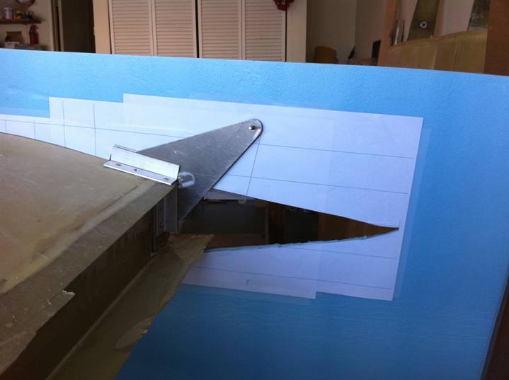
Mount to the Wing, the hinge bolt is the key reference
Mount all three templates to the wing and sight down them to insure they are all lined up porperly. Do the trailing edge points line up? If not determine why and correct the alignment.
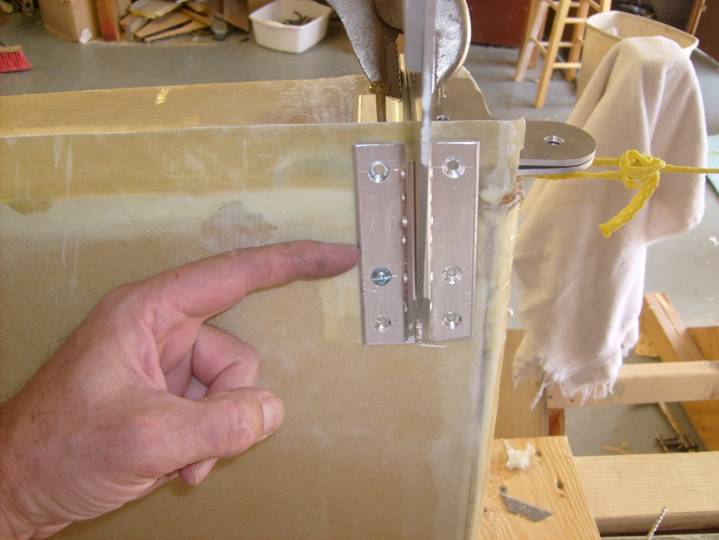
Insure flap hinge plate aligns with top of aluminum angles
Clamp the inboard hinge plate into position and insert a bolt through the aft spar mounting plate as shown below. Several bolts are used to align the angles with the holes in the aft spar plate. See below.
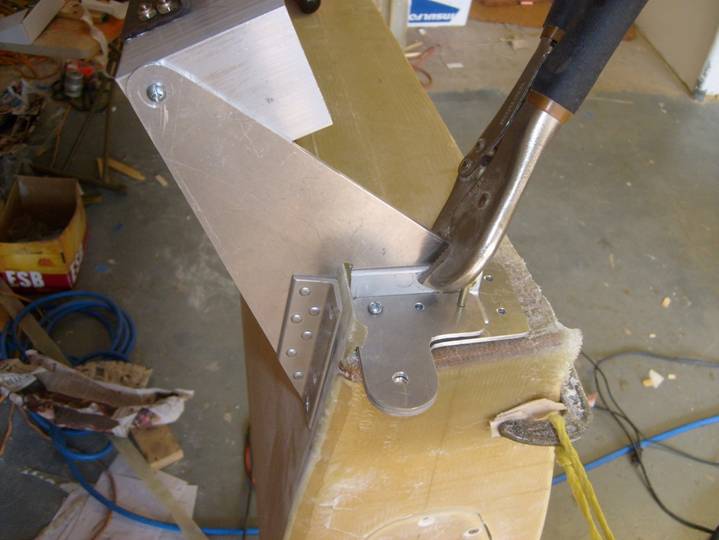
Inboard hinge plate assembly clamped in place.
Clamp the inboard and outboard hinge assemblies to the lower skin, but not to tight, if we clamp the hinges tight against the bottom skin the hinge assemblies will be forced out of co-linear orientation. Remember the hinge plate will not be flat on the lower skin and will not be perpendicular to the aft spar either. Clamp them just tight enough that one corner (usually the outboard forward corner) of the hinge assembly makes contact with the wing skin.
Inboard hinge pulled tight up against lower wing skin
Take your time at this step. We will be drilling two more holes to fully locate the flap hinges. These are located at the forward outboard corner of the hinge plate assemblies where they touch the lower wing skin. See the following series of photos to see the location of these screws on the inboard and outboard hinge assemblies.
Single screw pulling outboard hinge up agaisnt wing skin
Center hinge plate only mounts to wing skin
Single screw holding inboard hinge assembly to wing skin
Single screw holding outboard hinge assembly to wing skin
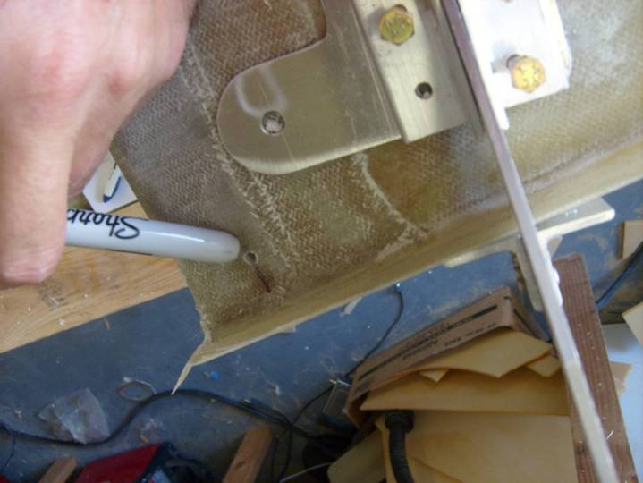
The hinges are now mounted in their proper position and we are ready to permanently locate them. Study the arrangement one last time to insure everything looks good. Then use a pencil to circle the hinge assemblies. Remove the hinges and jig from the wing and sand the areas where the mounting plates will be mounted.
See the following photo to get an idea of the flox landing area that will be created so the flap hinge will have a flat place to mount on the skin and aft spar.
Cover the aluminum angles of the flap hinge assemblies, all three including the center flap hinge assembly, where they come in contact with the bottom wing skin, with packing tape. Also cover the outboard flap hinge plate where it contacts the aft spar—see the photos at the bottom of this page for calirification.
Completed Flox Landing pad with holes drilled
Mix a thick flox resin mixture with some cabosil. Place a dollop on the three flap hinge assemblies where they will mount agains the wing (you have covered this area with packing tape). Coat the screws with wax or mould release. Remount the complete flap hinge assembly to the wing using the same three screws and clamps as needed. The flox should ooze out from under the flap hinge where it meets the wing skin. Skim away excess.
Insure the complete assembly has been returned to its proper position. Again do not tighten the mounting screws any more than required to just bring the hinges up into contact with the wing skin. See the above photo of the cured landing pad. You can see that there is thickness everywhere but the one corner where the hinge assembly contacts the wing skin. Let the flox cure.
Once cured and before removing the complete assembly from the wing, match drill the remaining holes through the bottom angles. Be sure to clear the rear spar, also be careful not to get the holes too close to the rear spar as it might be difficult to install the nuts later. Review the next photo for proper position of the screws through the wing skin and the one after that to see the proper position of the hole through the rear flange.
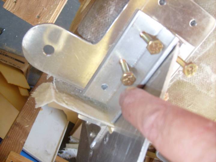
Standard hardware store bolts used during initial fit up
Before removing the complete flap hinge assembly from the wing, we will create the flox landing pad for the outboard flap mounting point on the aft spar. Cover the two aluminum angles used to attach the outboard flap hinge assembly to the rear face of the aft spar. The hinge plate should already be covered in packing tape.
Angles covered inpacking tape ready to install
Mix up a thick flox mixture as you did for the bottom wing skin and spear on the aft spar on both sides of the outboard flap hinge plate.
Thick flox Mixture smeared in Place
Clamp the two aluminum angles in place as shown in the following photo. Align the with the top of the hinge plate. Gentley press them against the aft spar to squeeze out the flox. Again do not disturb the alignment of the flap plate.
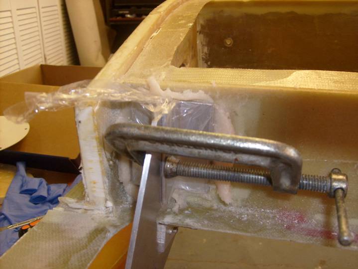
Angles clamped in place
Finished outboard spar plate mounting
Let cure. Drill the remaining holes through the aft spar and install bolts to hold this in place.
Finally, drill the two holes through the aluminum angle as shown above, and through the flap hinge plate. Repeat this on the inboard flap plate.
Remove the complete flap hinge assembly from the wing. Remove the packing tape, clean up the hinges and also the flox landing pads. Smooth the transisitions to the wing and remove any rough edges.
Congratulations your flap hinges are complete. Now is a good time to determine the proper length of the AN3 hardware required to hold each flap in place. Use a flat washer and fiberlock nut on each bolt (or screw as those through the bottom wing skin), so there are a couple of threads showing above the nut. Make a record of these and remove and store the flap hinges. It is much easier to determine the required hardware now, than when the top wing skin is on. We will not install the hinge again untill the wing is closed and we begin work on the flaps.
Complete.