Chapter 7 - The Wing
Section 4 - Wing Internals
Wing Access Panels
Each of the 3 bays, aft of the spar in the inboard wing section will have an access panel allowing for the maintenance of the internal components. The inboard most bay will have its panel in the middle of the A rib. The middle bay will have a rectangular panel centered in the bay just behind the spar in the bottom skin. The middle rectangular panel will allow the installation of a roll servo if desired. The outboard most bay in the wing center section will have a round access panel giving access to the outboard wing attach hardware and provide a mounting point for the pitot tube. The following descriptions and photos describe the three access panels separately, but it is more efficient to build all six (three on each side) at one time.
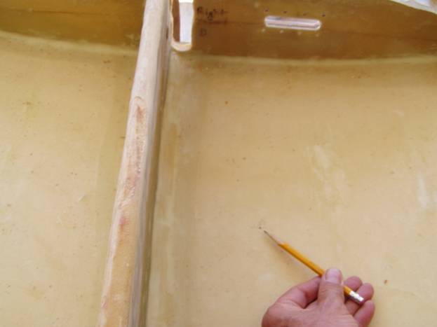
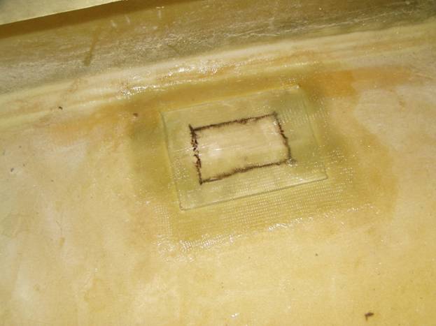
The panel in the middle aft bay will be created by cutting a rectangular 6” X 5.5” hole and will be finished with a .5” flange all the way around. This will result in a 5” X 4.5” inch opening with the long dimension oriented along the spar. The roll servo will be attached to the inside of this panel in the right wing. The forward edge of the panel cut is 2” back from the spar and it is centered between the two ribs. Drill two reference holes through the bottom skin from the top side using the spar and ribs as measurement points. Then flip the wing over and cut out the panels.
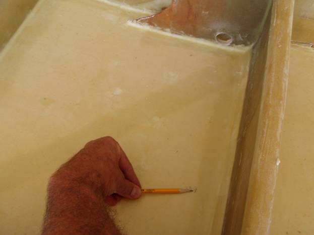
Reference holes drilled through the Skin
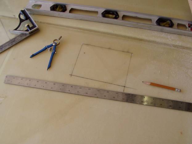
Draw panel outline on bottom of the wing
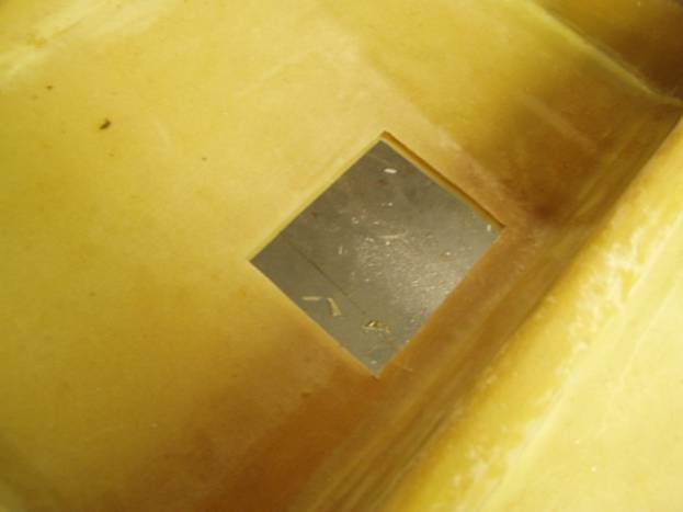
Cut the panel out and remove ¼” of foam from the edge
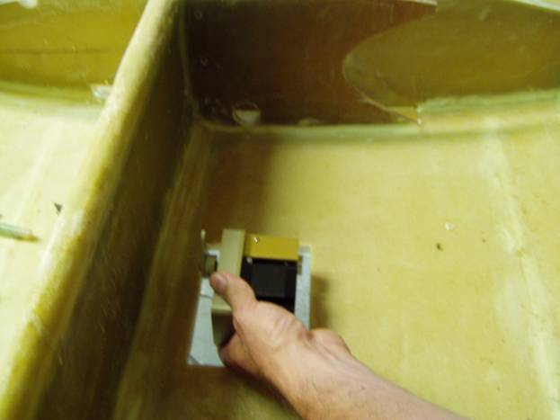
Approximate position of the Roll Servo
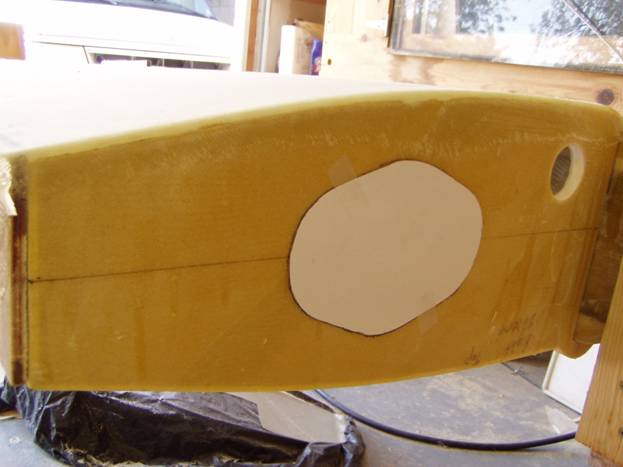
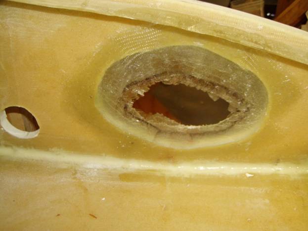
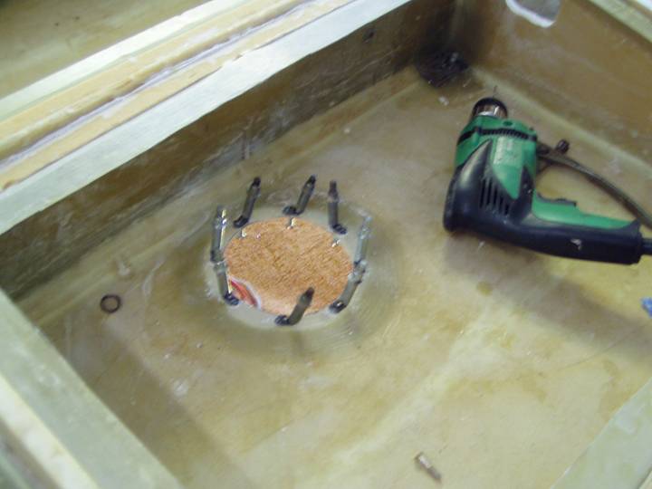
The outboard most panel is circular, 6” in diameter allowing for a 5” opening with the .5” mounting flange. The forward edge of the hole is made 1.5” behind the spar and centered between the two outboard wing section mounting bolts. The easiest way to mark this hole is to drill a reference hole through the bottom wing skin from inside the bay. Drill 4.5” back from the spar and 16” outboard of the C rib. Then flip the wing over and draw a 6” circle around this hole and cut out.
Reference hole
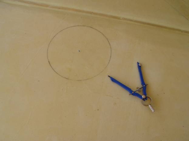
Draw the panel outline
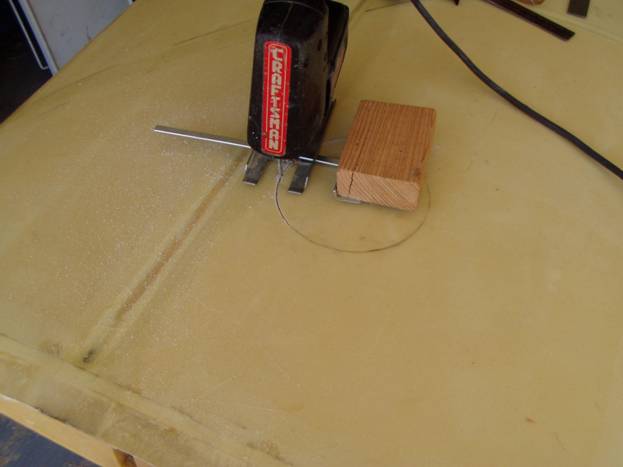
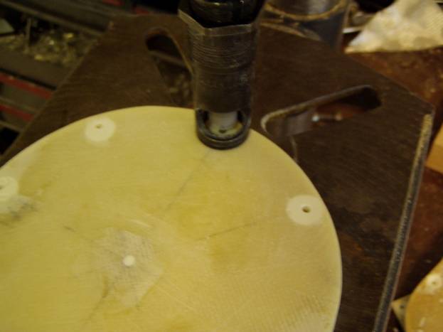
Simple jig to cut a circular hole
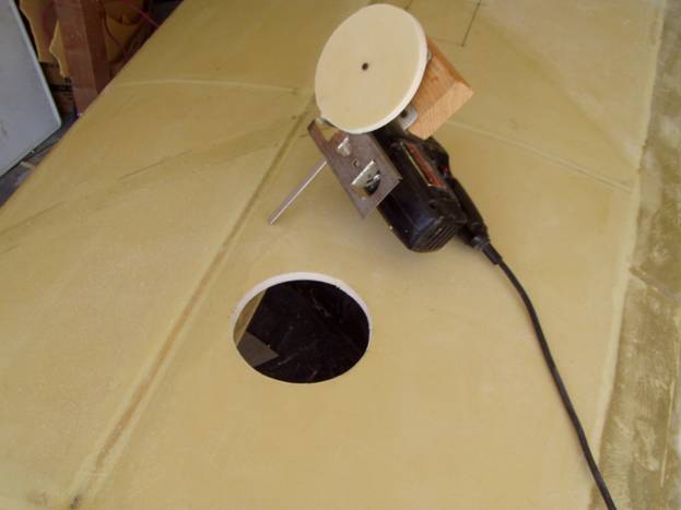
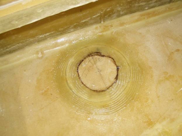
Nice panel cut
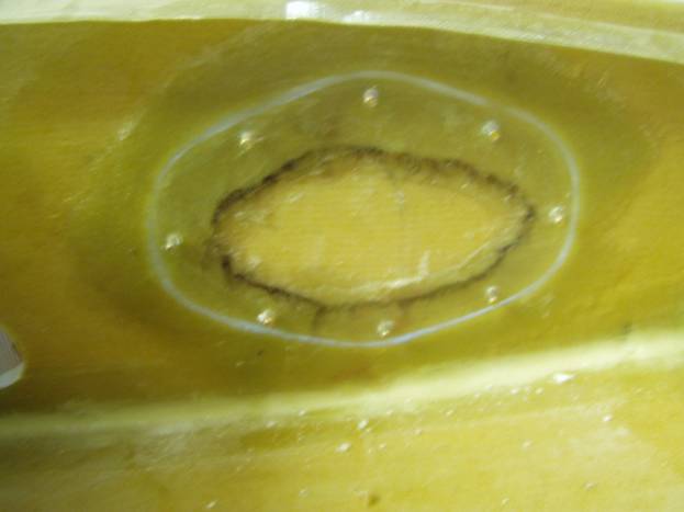
The panel in the A rib is an oval shaped panel similar to the one in the aft starboard side of the fuselage. It measures 6” X 4.5” with its forward side 6” back from the spar and is centered up and down on the rib. There is a .5” flange all the way around. This panel will not be seen so it does not need to be attractive.
Pattern for the A rib access panel
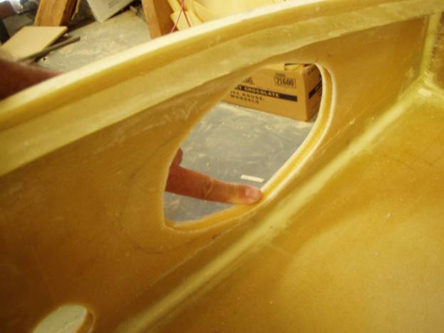
Cut out the panel and remove the foam core
Next we will work on the panels themselves. As mentioned before it is easier if we finish all 6 panels at the same time. 8 ea. 1032 flat head AN507 screws are used to secure the panels (use MS24694S56 Screws and MF5000-3 Nut Plates). Be sure you have properly labeled each panel so they do not get mixed up and mark front/back, top/bottom. Mark the location of the eight holes on each panel by measuring in 3/8” from the outside edge and then 8 equally spaced points around each panel. It is important that each panel goes in with the same orientation it was cut out as there may be some variation in skin thickness in the wing skin.
Once the hole locations are marked, drill an 1/8” pilot hole all the way through the panel. Then drill a ½” hole only through the outer fiberglass layer and the foam. Clean out the foam from the hole. The panels should now look like the ones in the following photo.
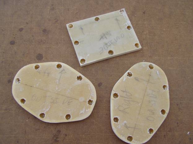
Panels Drilled
Mix up a thick micro and fill the holes flush with the top surface. It is best if the micro is a little proud of the surface so we can sand the cured micro flush with the out side surface.
Redrill the 1/8” pilot hole all the way through the panel. Notice in the following photo how a stop block is used on the drill press to insure a uniform 3/8” from the edge of the panel.
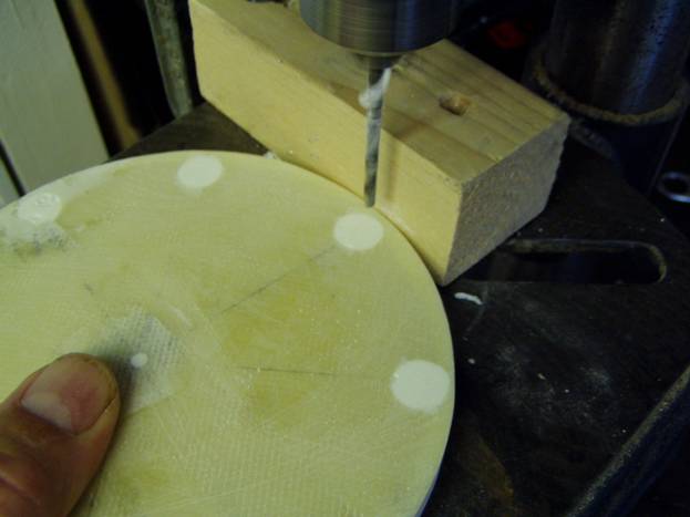
Redrill pilot holes
Now, use a countersink tool to countersink the holes for our AN507 flat head screws.
Countersink the holes
Finally, drill the holes out to the final 3/16” diameter.
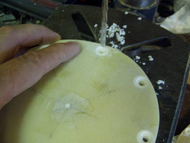
Final drill to size
Test fit a screw in each hole to insure you have the proper counter sink depth.
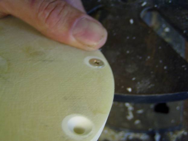
Completed holes
Now wrap the panel in packing tape. Use hot glue and stir sticks on the outside of the panel and the wing skin to temporarity hole the panel in place. Use small pieces of scrap stir stick to equally space the panel from the edges of the hole.
Use a marker to draw a line about 1 inch inside the edge of the panel. Then layup a 5 layer laminate all the way around the edge extending an inch onto the panel and the inside wing surface.
Let Cure.
Fiberglass Flange
Fiberglass Flange
Fiberglass Flange
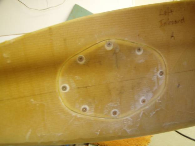
With the panel still in place, drill the 3/16” holes all the way through the flange.
Holes Drilled through flange
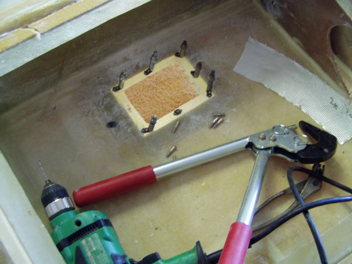
Installing Nutplates
Installing Nutplates
Install nutplates on the inside of the flange using flush rivets.
Trim the flange about 1/8” inside the nutplates. Insure you can comfortably insert your hand through the holes.
Completed Panel
Good Job, panels are complete.