Chapter 7 - The Wing
Section 4 - Wing Internals
Aileron Idler and Bellcrank Assemblies
The control stick assembly under the seat attaches to the aileron control system in the wing via push/pull tubes. There are three tubes between the stick and each aileron. The first attaches between the control stick and an idler, the second attatches to the idler and the aileron bellcrank, and the third, of course, connects the aileron bellcrank to the aileron. The design allows for an autopilot servo to be attatched to one of the idlers. The aileron bellcranks have a special geometry that provides for a non linear aileron response. This geometry results in a full upward deflection of one aileron of 22.5 degrees and a full down deflection of the other aileron of 18 degrees. Also, the ailerons are hinged at the top so less aileron is presented to the air below the wing that above, creating less drag. These features minimize the effect of adverse yaw produced by the downward dragging aileron. In this manner the aircraft will requires less rudder to provide a coordinated turn.
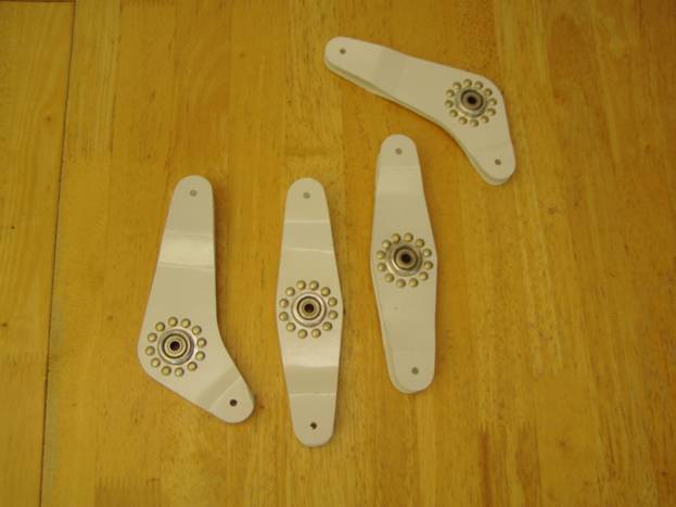
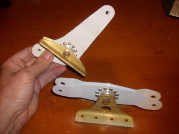
Below is a photo of the completed bellcranks mounted in their brackets. We will first fabricate the bellcranks, then the mounting brackets and then finally assemble them.

Completed Bellcrank and Idler Assemblies
Below is a photo of just the bellcrank and idlers, we will build two of each. If you have fabricated the elevator bellcrank located in the aft end of the control tunnel, you will be familiar with the construction of these. However, follow the procedures that follow carefully as it is important that the geometry of the bellcranks and idlers are accurate to the mechanical drawings.
Completed Bellcrank and Idlers
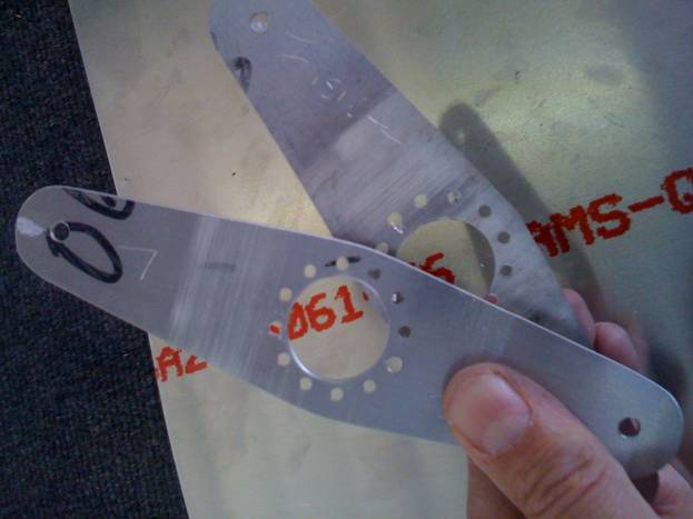
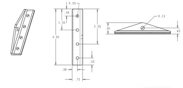
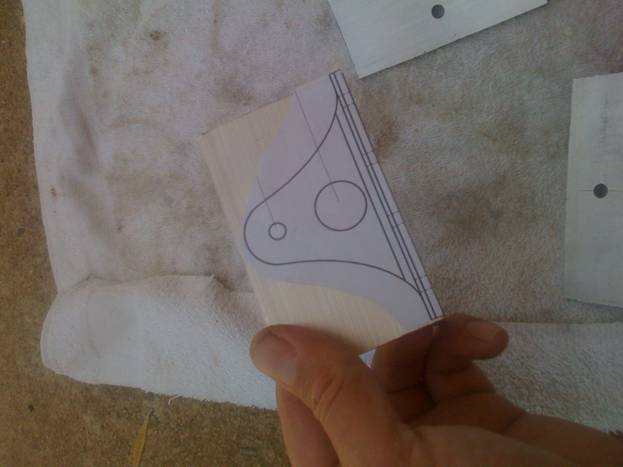
First print out four copies of the following A sized drawing. These are fabricated from .062” thick 6061T6 sheet.
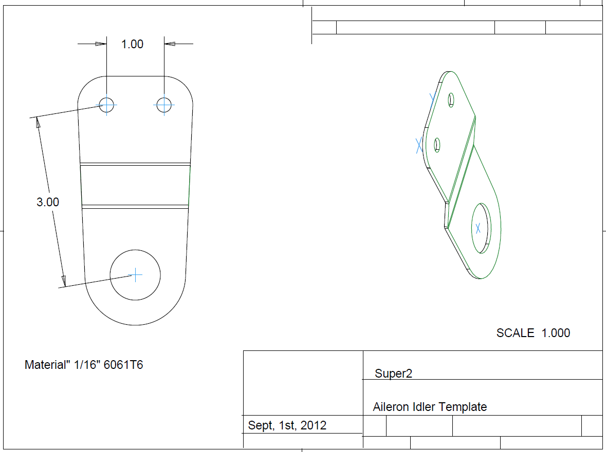
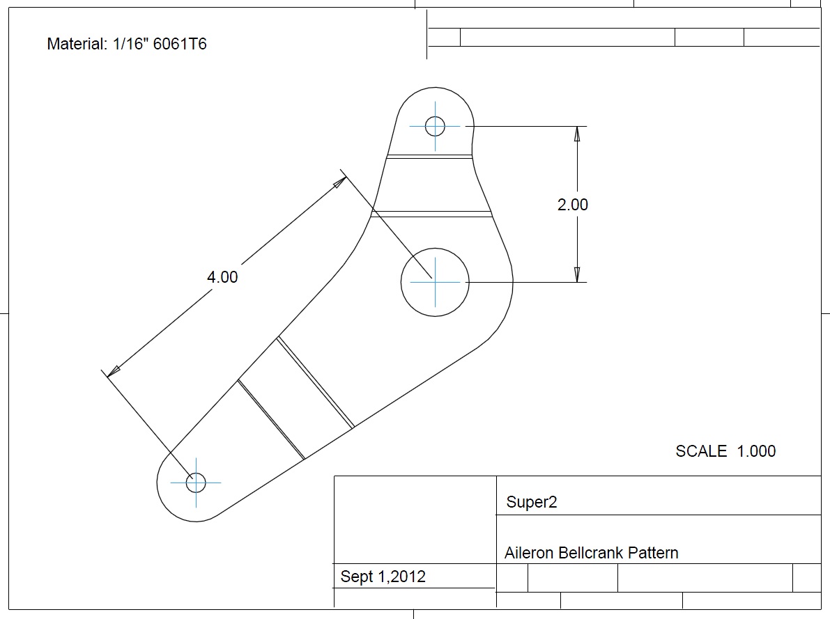
Bellcrank Aluminum Drawings
First, using a shear cut the eight pieces of aluminum oversized.
It is best if the large center hole is drilled ( or punched) first, then the paper pattern is glued using a glue stick using the large hole as an alignment guide. Hold the aluminum up to the light and align the paper pattern.
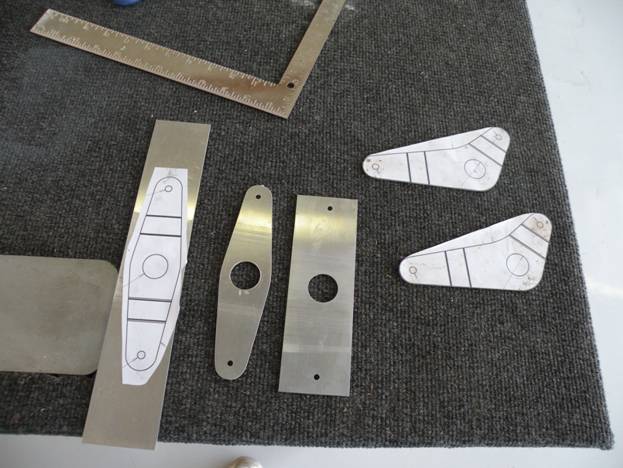
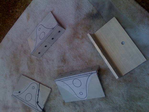
Next, carefully mark, center punch and drill the ¼” holes (the print shows them to be 3/16” hole, but we will use AN4 hardware which requires ¼” holes). It is best if you make one perfect part, then match drill the rest.
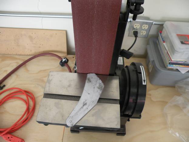
Next use a shear to trim the majority of the aluminum away. Use a table sander to finalize the outside shape. These should be sanded in pairs as all operations from this point forward will be on pirs of parts. Be sure to mark them as such, inside and out as well.
Form to insure proper alignment of bearing
Alignment guide
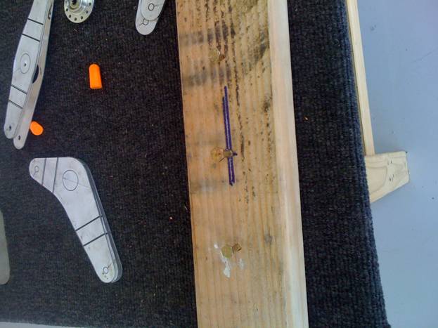
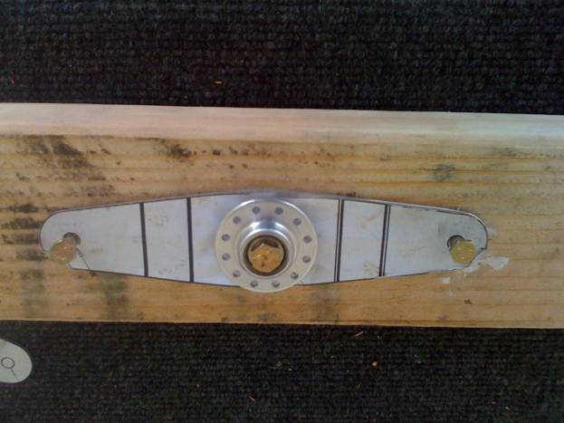
First let us align the bearing in the idler. Take a piece of wood and drill two holes exactly 6” apart, you can use one of your idler parts to drill the two 1/4” holes. Then precisely measure and drill a ¼” exactly between the two. Make it perfect—make a new alignment guide if you have to.
Take two matching idler parts and secure them with the two outside bolts to the alignment guide. Next secure the bearing in place with the center bolt and drill the holes, cleco-ing them as you go.
The following photos shows the progression of steps to insure proper alignment of the holes in both parts.
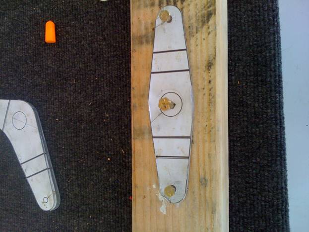
Alignment Guide with first part
Center bolt positions Bearing
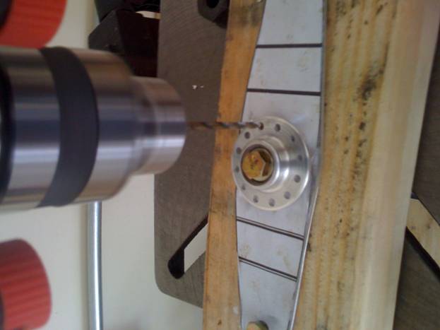
Drill the First Hole
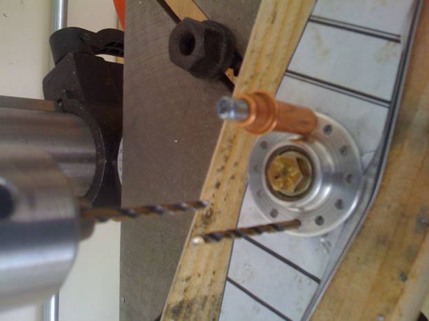
Use a Cleco to hold bearing in place and Drill Second Hole
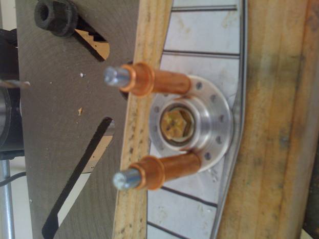
Cleco and continute Drilling All Holes
A completed Pair, all holes match Drilled
Good Job. The next step is to repeat the process for the Aileron Bellcranks.
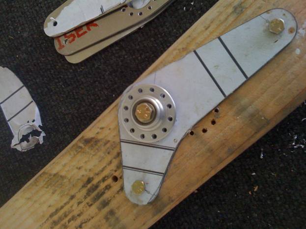
Aileron Bellcrank Mounted on the Alignment Guide
Once all of the parts are drilled and all edges are deburred, it is time to bend them to fit the rod end bearings. The places to bend the parts are marked on the paper patterns. The bearing is only ½” thick and with the thickness of the bearing, the bends are not very great. Place the part in a vise and use a wooden block to evenly push the part over about 10 degrees to create the bends. Be extra carefull to maintain the inside of the parts, and keep them a matched set.
When you are happy with your bends it is time to clean the parts up, paint them. . Use AN470AD4-7 rivets to attach the bell crank bearings to the aluminum halves.
Finished Set of Aileron Bellcranks and Idlers
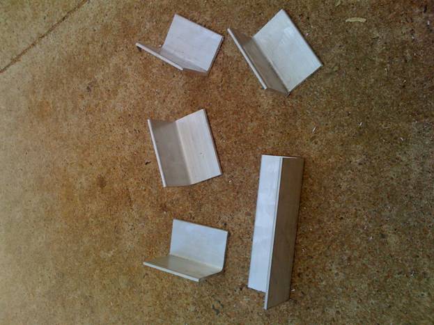
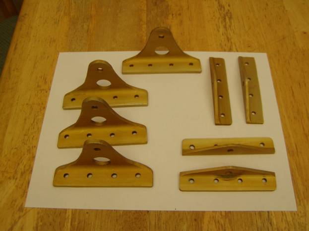
This completes the first step, let us move on to brackets that mount these bellcranks to the wing structure. Below is a photo of a finished set of brackets, note there are a total of 4 of each type.
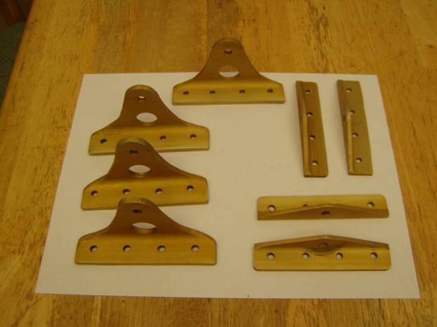
Completed Brackets
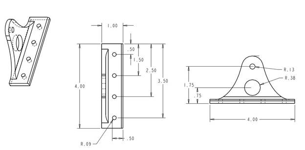
Aileron Idler Bracket
Aileron Bellcrank Bracket
Print out the following prints and make four each Aileron Idler Bracket and four each Aileron Bellcrank Brackets.
Use the 2 foot 6061T6 2 ½” X 2 ½” X 3/16” Alum Angle (ACS 03-00007-2) for the Idler Brackets and
2 foot 6061T6 1” X 1” X 1/8” Alum Angle (ACS 03-48000-2) to fabricate the Bellcrank brackets. It is best if these are fabricated in pairs and the ¼” holes are matched drilled. Use a punch to mark the bottom of the parts to insure they are not mixed up later. I punched three dots in the bottom of two and three dots in the bottom of the other.
Cut to Length
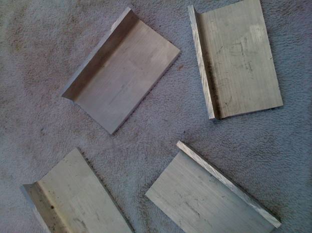
Edges cut to Size
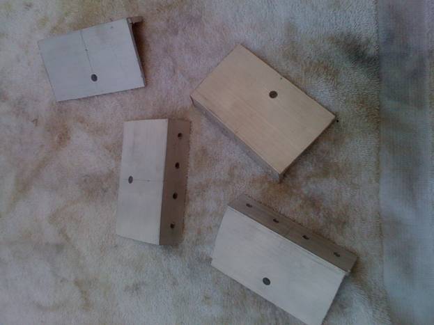
Holes are Drilled
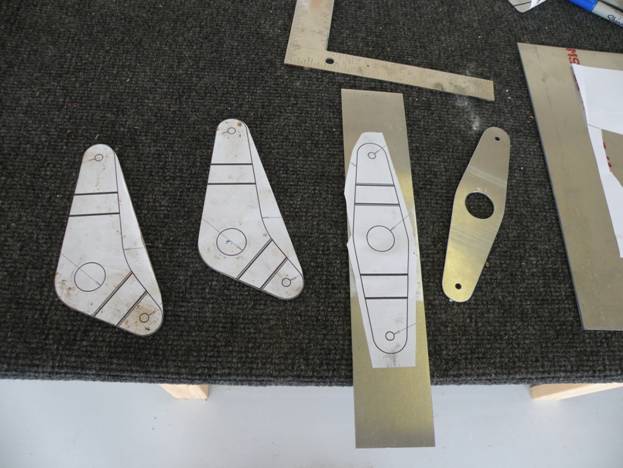
Paper Patterns are attatched
Preparing to rough Cut
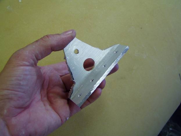
Rough cut Idler Bracket
File and sand the parts to shape. Deburr and finish. I used MetalPrep and an Alodine solution to finish my parts. You can do the same or paint them.
Completed Brackets
The Bellcranks assembly is then clamped between the aluminum angles using a AN4-13A bolt, three AN960D416 washers and a AN364-428A nut. The angles are attached to the ribs using AN3-11A bolts with AN960-D10L washers andAN364-428 nuts.
The Idler assembly uses a single AN4-12A bolt, three AN960D416 washers and a AN364-428A nut.
The rod end bearings (the control tube) are attached to the bellcranks with AN-11A bolt , a AN960D416 washer and AN364-428A nut.
Finished Assemblies
Complete. Good Job.