Chapter 7 - The Wing
Wing Internals
Once we have glassed the bottom of the wing we are ready to start work on the internal features of the wing. These include:
- Fuel Senders
- Fuel Vents
- Fuel Strainers
- Fuel Drain –including pressure relief and overflow protection
- Slosh Gates
- Gear Brake lines
- Flap Hinges
- Aft Spar to fuselage attachment Bracket
- Electrical – pitot heat, nav lights, strobes, trim servo
- Aileron Controls – push/pull tubes and bellcranks
- Auto Pilot roll servo
- Pitot system
- Access Panels
- Fuel Caps
- Gear Leg Attachments
- Tie Downs
Section 4 - Wing Internals
Collect the following parts for the wing:
- 2 each An867-3 Welding flanges for the fuel drains
- 2 each An867-1 Alum Welding flanges for the fuel outlet
- 2 each vacuum relief valves – fuel and pressure relief valves (ACS 52763)
- 2 each finger strainers – (ACS p/n 05-17700)
- 2 each fuel drains (ACS 05-01865)
- 2 feet MS20257P Hinge material
- 2 each 4 foot sections 6061T6 Tube 1” X .049 (ACS 03-36610-4)
- 4 each push rod tube ends (Van’s Aircraft part number )
- 4 each xxxx Rod Ends
- 2 foot 6061T6 2 ½” X 2 ½” X 3/16” Alum Angle (ACS 03-00007-2)
- 2 foot 6061T6 1” X 1” X 1/8” Alum Angle (ACS 03-48000-2)
- 88 each MF5000-3 Nut Plates
- 48 each MS24694S56 Screws
- 40 each MS24693S273 Screws
- Each AN3-10A Bolts
- each AN3-11A Bolts
- each AN4-10A Bolts
- 2 each AN4-13A Bolts
- 2 each AN4-15A Bolts
- 6 each AN4-27A Bolts
- 50 each AN970-3 washers
- 12 each AN970-4 washers
- 100 each AN364-1032A stop nut MS21083N3
- 10 each AN364-428A stop nut MS21083N4
- 300 each AN960-10 flat washers
- 100 each AN960-416 flat washers
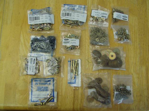
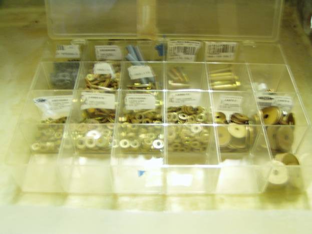
Hardware in a Labeled Parts Tray
Note: The AN3 hardware used to attach parts to the wing structure may vary in length from the values stated in this manual. I have a hardware kit that I purchased from Aircraft Spruce that contains a collection of most sized hardware and a bolt length gauge. I will then use the proper length hardware which requires a couple of threads showing past the bolt, but not too many more as we do not want to run out of threads.
Parts Prep:
We will now modify a few of the parts to better meet our needs. There are two aluminum welding flanges that need some work. The smaller aluminum welding flanges with the 1/8” NPT holes are used for the fuel drains. The outer raised ridge is ground down as shown in the following series of photos.
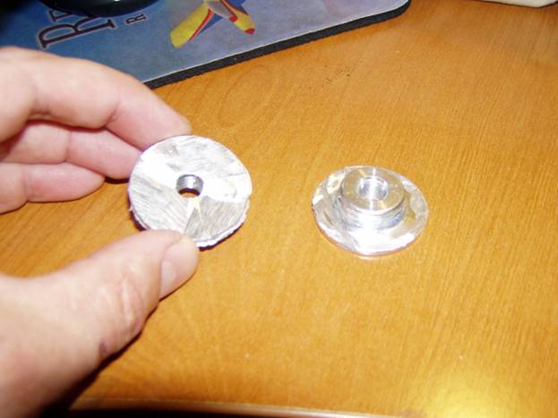
Raised lip on the smaller flanges are cut off
The larger aluminum welding flanges are used for the fuel outlet with at finger strainers installed. These need to ride low in the tank so we need to modify them. The fuel outlet flanges are cut as the following photo shows and again the entire part is roughened up with the grinder.
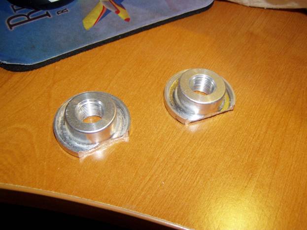
Fuel Strainer Welding Tabs cut
Slosh Gates
To make the bond on slosh gates, cut sections of the MS20257P piano hinge material 5 inches long. Permanently swage the hinge pin in place. Cut a small piece of aluminum sheet, .020 or so, ½” X 1” and bend it into a small angle to provide an upper stop. This will prevent the slosh gates from sticking open. Finally cut strips of pre-cured 2 layer fiberglass laminate the size of the hinge . These are then riveted together as a unit using flat head rivets. Countersink them into the procured laminate so we have a flat surface on the back to bond to.
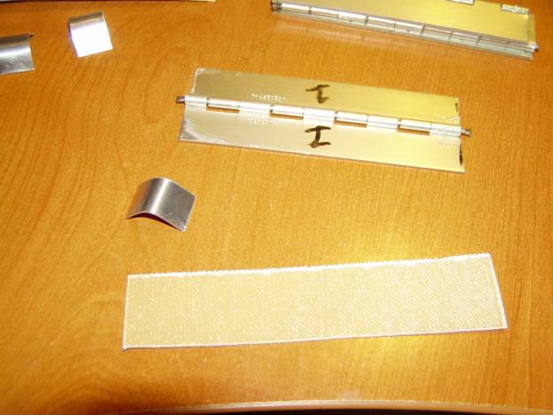
Parts to make Slosh Gates
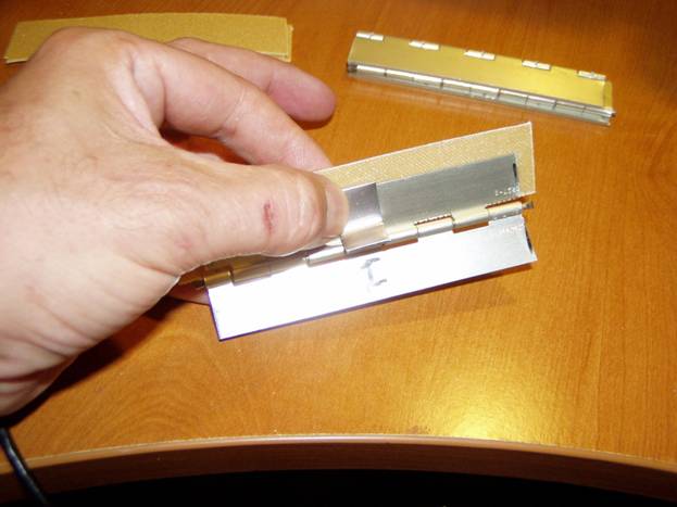
Slosh Gates

Slosh Gate Bonded in Place
The fuel vents are fabricated from sections of 1/8” aluminum plate and aluminum bulkhead fittings. These can be obtained commercially or fabricated by welding bulkhead fittings to aluminum.
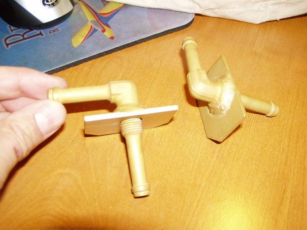
Fuel Vents
It is important to note that epoxy does not bond well to alodined aluminum. The parts in the photo will need to be sanded with red scotchbrite in the area where we use epoxy and flox to seal them.
There are a handful of aluminum parts we need to fabricate including the bellcrank assembly, idler assembly; flap hinges and rear spar attach brackets. We will work on these next.