Chapter 7 - The Wing
To install the aft B rib and its companion, the BB rib, we need the upper gear leg.
Section 3 - Wing Assembly and Bottom Skin
Main Gear Legs
It is best to finalize the fabrication of the gear legs after the wing is built and has been mounted to the fuselage in order to insure that the toe in/toe out is absolutely correct. The upper gear leg is fabricated from a 2 foot section of 1.5” O.D, .120” 4130 steel (Aircraft Spruce part number 03-09300). The integrated bushings are fabricated from 3/8” O.D, .058” 4130 steel (aircraft spruce part number 03-01400). 1 foot will be enough for the bushings for both legs.
Start by drilling three 3/8” holes though the gear leg, the first one is 5/8” from the end of the tube and the two other holes are 2.5” inches from each other. Use a V-Block with a drill press to insure that the three holes are centered to the gear leg. Clamp a level to the tube to insure the three holes are vertical with respect to each other.
Then use a ½” drill bit to counter sink the holes as shown below, but not all the way through as we need the material to hold our bushings in place.
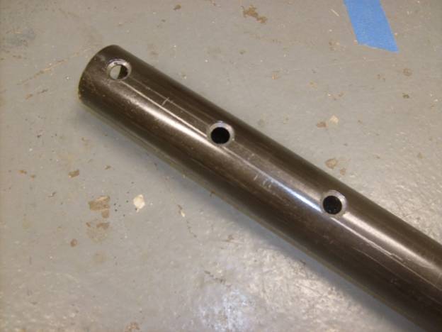
Three mounting holes drilled and countersunk in upper gear leg
Cut three sections of the bushing material (3/8” .058” 4130 steel tube) 2 inches long and position in each of the three holes with a section protruding beyond each side.
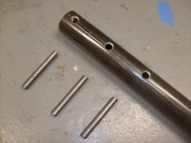
Bushing material cut and ready to insert
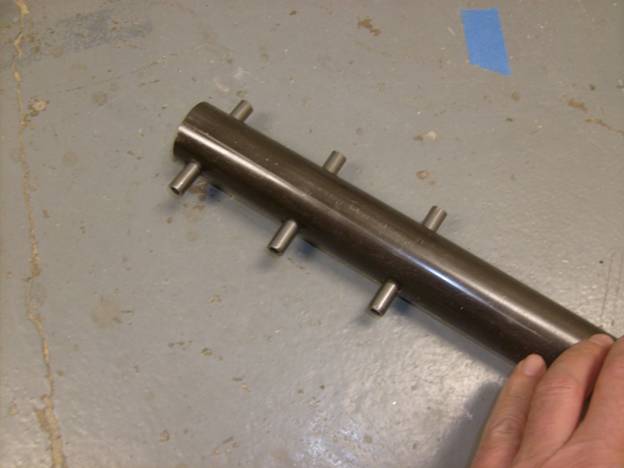
Bushings installed and ready to weld
Weld the bushings in place, then use a hack saw and grinder to cut the bushing off flush with the outer surface of the gear leg. Inspect the welds. Use a reamer if necessary to insure the holes through the bushings are clear.
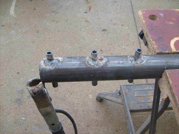
Bushings welded in Place
Paint the upper gear leg with primer. Use standard ¼” bolts, washers and nuts from the hardware store for initial assembly. The nuts will be assembled and removed numerous times and aircraft nylon lock nuts will be worn out by the time we need to use them the final time. We will use standard AN hardware for the final install. Below is a photo of all the parts required to install the last of the ribs.
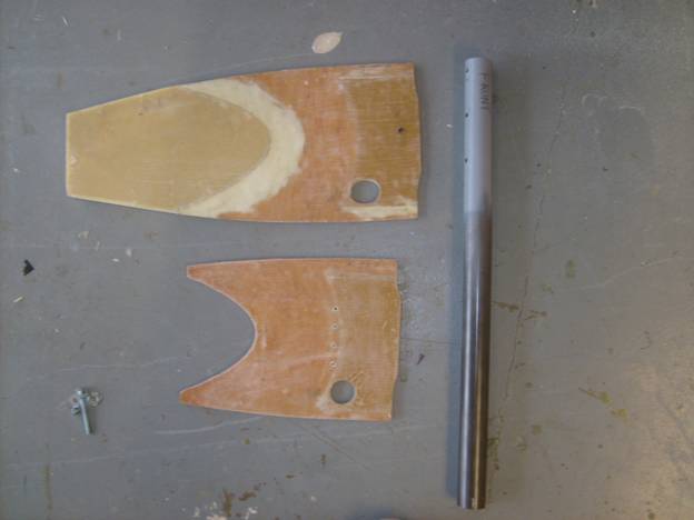
Gear leg components, aft B and BB ribs ready for install
I used a couple of lightweight bunji cords to temporarily hold the aft B rib in place—clamps work equally well. The aft B rib is aligned with the edges of the A rib and the C rib up and down. Several long straight edges are used to check the fit to the top and bottom of the A and C ribs. Carpenter levels work well. Insure the B rib is square to the spar and the proper distance from the A and C ribs. You should have marks on the spar to define its position.
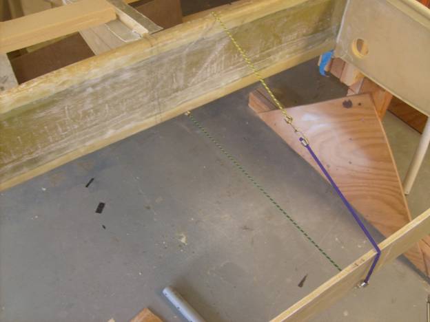
The small bunji cords are used to hold the aft B rib in place
Place the aft B rib in place and grind as needed
The aft B rib will need to be ground down to clear the top and bottom spar caps. When it is positioned properly the aft spar will be straight between the A and C ribs which should have already been bonded into place. The top of the B rib should not protrude above the A or C rib, nor should the bottom of the rib, if it does grind it a bit. Remember, the A and G rib will define the shape of the wing. When in doubt, make the other ribs a bit lower, not taller.
Once happy with the fit of the B rib, mark a lineon the rib, back from the spar, centered between the top and the bottom of the rib. The line should extend about 2 inches back from the spar. Transfer this mark to the spar to ease the reinstallation of the rib. This line will mark the position of the center gear leg mounting bolt in the up and down direction. Also mark the location of the B rib on the trailing edge.
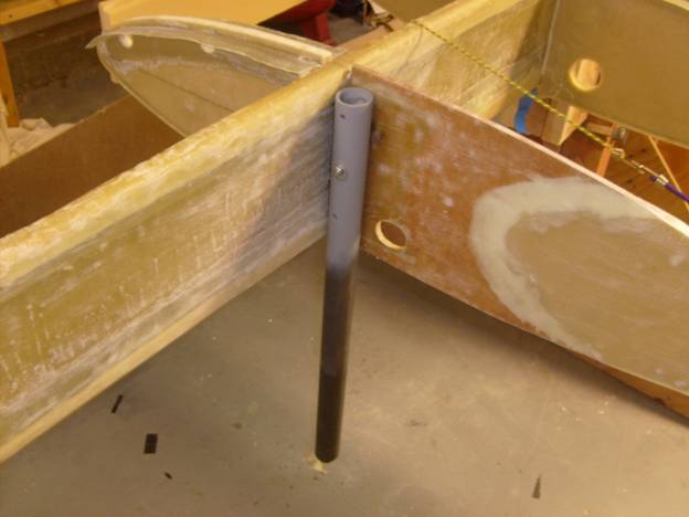
Next hold the gear leg in position on the outboard side of the B rib. It should be vertical and spaced about 1/8” behind the spar caps. That is it should not touch the spar. I used magnetic levels that helped me orient the gear leg. While it is in place use a scribe or a ¼” drill bit through the center hole and mark the position of the leg on the B rib. Finally drill the first hole in the B rib in the center gear leg position where the horizontal line meets the mark you just made.
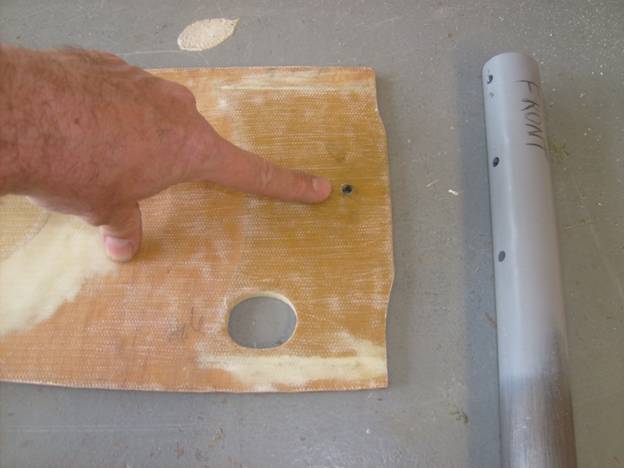
First hole drilled in the B rib
Bolt the gear leg to the B rib and install the B rib into its position
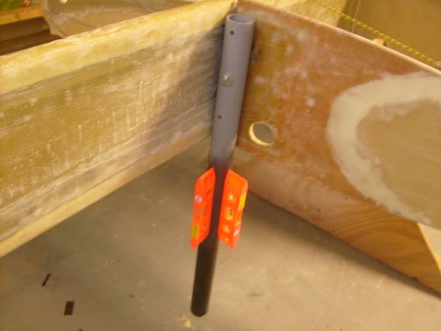
Magnetic levels to insure the gear leg is straight up and down
With the gear leg bolted through the first center hole in the B rib, level up the leg and insure the rib is positioned properly. Drill the two remaining holes in the B rib.
Adjust the position of the B rib one last time, then bond it into position using dabs of 5 minute epoxy and flox. Install the remaining two bolts to hold the gear leg in place.
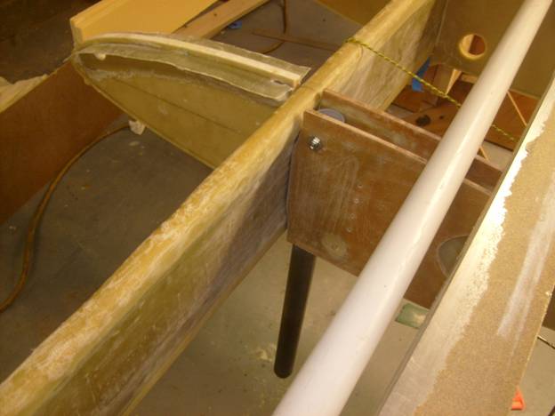
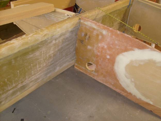
Position the BB rib outboard of the B rib
Next remove one of the bolts holding the gear leg in place. Position the BB rib to the outboard side of the gear leg. Use a similar technique to position the BB rib as was used to position the B rib. In the above photo you can see the use of several straight edges to hold the BB rib in place. It needed to be trimmed to clear the spar caps as was the B rib.
Once you are happy with the position of the BB rib, drill a hole through the B rib and gear leg and through the BB rib.
Remove the BB rib, remove another bolt from the B rib and gear leg. Then bolt the BB rib back into place using the hole drilled through it, and drill the next hole. Repeat this process one more time to drill the last hole.
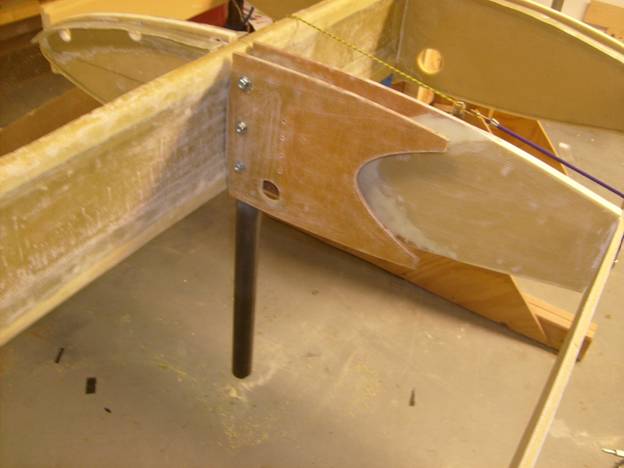
BB rib bolted in place
Finally remove the BB rib and then reinstall it with washers installed between the inside of the BB rib and B rib. There needs to be an additional .100” between gear leg and each rib as we will add fiberglass later and we need room for it. I used two .060” washers on one side and one .060” washer on the other side to get the approximate space between the two.
Bond the BB rib into place with 5 minute epoxy and flox. Once cured, the gear leg can be removed and set aside.
All of the ribs should be installed at this point. It is now time to go back and check everything. Make sure the wing is level and repeat all of the alignment measurements. The wing is only held together with dabs of 5 minute epoxy and flox and we can still bust things apart and reposition them. Make sure the G rib is well supported and all the ribs are level. Are the trailing edges straight? Sight down the wing, do any ribs look out of place?
Once completely happy with the position of the entire assembly, use a thick micro and epoxy mixture to put a nice 3/8” radius between all of the joints, spars, ribs and trailing edges. Then cut long strips of BID 3-4 inches wide and apply a two layer BID laminate so the bond is 1.5-2 inches onto each side of the joints. Remember not to bond the outboard wing section into place. You may need to remove the outboard wing section at some point to gain access to some of the joints.
We will now add the laminates between the aft B and BB ribs and the spar. this will complete the structure that will transfer the landing loads to the spar. First, sand the foreward side of the aft B and BB ribs from the spar to about 8 inches back. It is tight between the ribs, but this is important. Scuff up the fiberglass well. Sand the spar 12" to each side of the B and BB aft ribs. Then clean these area with acetone. On a sheet of plastic on your work bench create a 6 layer BID layup 7.5" square. Paint the spar between the ribs with epoxy and then press this 6 layer fiberglass between the B and BB ribs and the spar inbetween. This will create a U shaped layup the full height of the spar laying over the B and BB ribs where the upper gear tube will mount. Work out the airbubbles, use a hot nail to open up the drill holes and then let cure. Redrill the leg mounting holes.
Now we will add the laminiates on the outsides of the B and BB ribs onto the spar. This will be a 10 layer laminate created with 5 pairs of staggered layers. Start by cutting 2 each the following rectanges of BID. this example is for one layup. 7.5" X 4", 7.5" X 7", 7.5" X 10", 7.5" X 13" and 7.5" X 16". Using a sharpie marker, draw a vertical line in the middle of your sheet of plastic on your work bench. Label the right side - rib, and the left side spar. Layup the first two layers on the plastic using the largest strips of BID overhaning 6 inches onto the rib side of the line and 10 inches onto the spar side of the line. Next layup the next longest strips overhanging overhaning 5 inches onto the rib side of the line and 8 inches onto the spar side of the line. Next layup the next longest strips overhanging overhaning 4 inches onto the rib side of the line and 6 inches onto the spar side of the line. Next layup the next longest strips overhanging overhaning 3 inches onto the rib side of the line and 4 inches onto the spar side of the line.Finally, layup the last strips overhanging overhaning 2 inches onto the rib side of the line and 2 inches onto the spar side of the line. When you are happy with the layup, pick it up leaving it on the plastic, fold it at the vertical line and press it into place between the spar and the rib. Work out the airbubbles, use a hot nail to open up the drill holes and then let cure. Redrill the leg mounting holes.
Wow, big step completed. We are ready to begin sheeting the wing.