Chapter 2 - Fabricating the Tail
Section 2 - Vertical Stabilizer Elevator Pulley
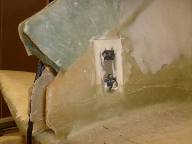
Once the vertical stab has been glassed we can add the features that support the pulley located in the vertical stabilizer. The Elevator cable is routed up and over this pulley, attaching to the elevator bellcrank on the forward side and the elevator itself on the aft side. Refer back to the drawing for the elevator vertical side stab and you will remember that there are two holes positioned above the front tab. The larger one is for an AN4 bolt that holds the pulley, and the smaller one above it is for an AN3 bolt that acts as a cable keeper. The Ralmark MS24566-3B pulley is used in several places in the aircraft, here in the vertical stab and in the control tunnel to route the rudder cables. The pulley in the vertical stab is mounted on an AN4 bolt and there are two aluminum spacers and AN970-4 flat washers that space it in the middle of the stab. There is a nut plate on the other side. There is a second AN3 bolt that goes through the stab just above the pulley and should be about 1/16” above the pulley not touching it and acts as a safety restraint for the top elevator control cable, keeping it from jumping off the pulley.
Nut Plate Side of Vertical Tail
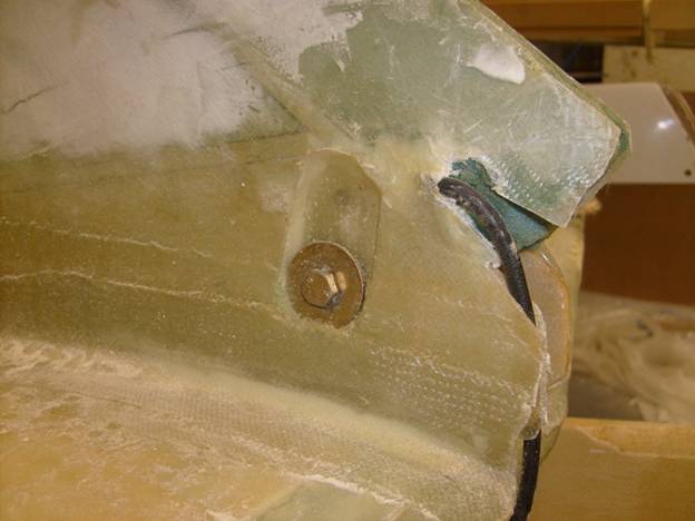
A nut plate is fashioned from 1/16” aluminum plate with the hole locations defined by the above mentioned drawing. Drill the holes all the way through the vertical stab and then cut a notch into the side of the vertical stab. Lay in 3 layers of BID into the recess. Micro and then glass the nut plate into position as shown. On the opposite side of the vertical stab, the foam is removed and a recessed area is likewise glassed in with three layers of BID. Re drill the holes when the glass has cured. Notice how the com antenna is routed so it will not interfere with the free movement of the elevator cable.
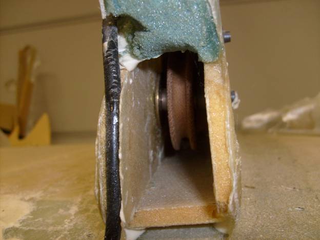
View of Pulley
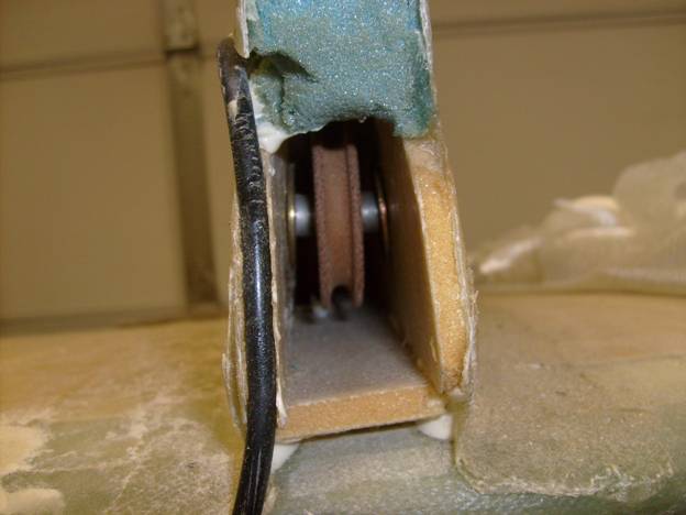
View of Pulley
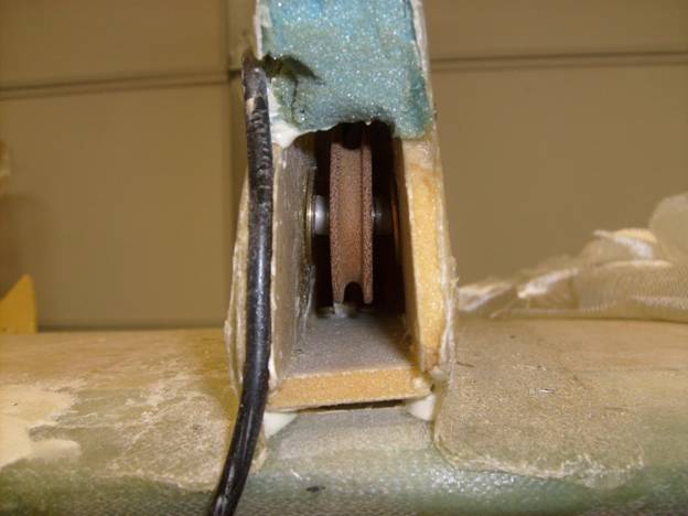
Notice cable routing clear of elevator cable
Bolt Side of Vertical Tail
Let cure.