Chapter 4 - Finishing the Tail
p>Section 2 - Building the Elevator
Elevator Assembly
Positioning the End Rib
The end ribs can be attached first. The photo above shows how mixing sticks can be used to achieve the desired gap. We want a 1/4" at this stage. If the spar is not long enough do not worry, clamp the end rib in place, then use a mixture of 5 minute epoxy and flox to fill in the gap and create a fillet to temorarily attatch them They only need to be tacked into place at this stage. another technique is to accomplish this is to use CA glue. Apply the CA to both surfaces, then align the parts precisley with gloved fingers, then spray with CA accelerator. A 1/4" gap may seem excessive at this point, but we are going to wrap a number of layers of carbon fiber skin over this rib to build up the strength of this area as it will carry the weight of the elevator counter balance latter.
Positioning the Driving Ribs
Cut a notch in the top and bottom rear flange on the horizontal stabilizer exactly in the middle. this notch will be used to locate the elevator control belcrank.
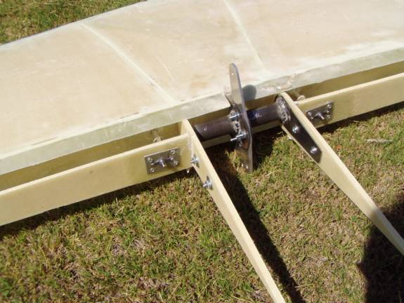
At this point we are ready to tack on the driving ribs. It is easier if you add the hard points in these two ribs now. Look further down this page on how to add the hardpoints in the driving ribs, then return to this step. Mark the driving ribs as to inside and outside.
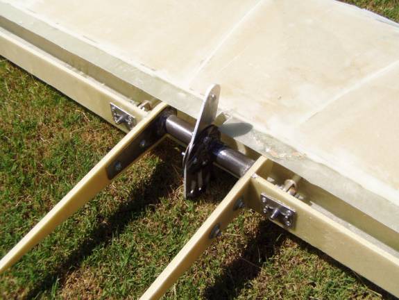
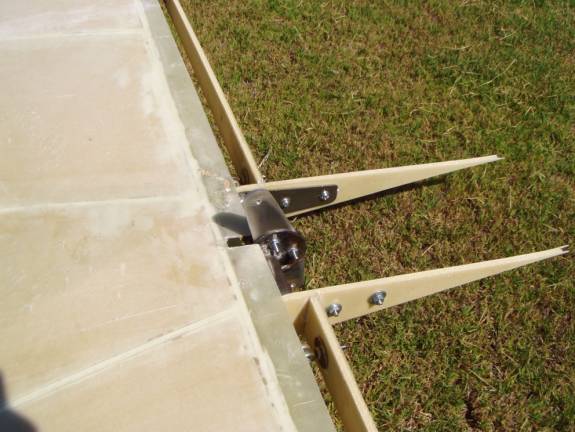
Bolt the two driving ribs, elevator weldments and elevator bellcrank together as a unit. The multiple holes in the bellcrank face downward. Insure that this assembled unit is square, if not tweek the weldments until it is so. Using the two driving ribs bolted together in this way, trim the two elevator spars so the rib assembly is located exactly in the center of the horizontal spar. Line the driving ribs up with the spar using the pencil marks on driving ribs. There should be a small gap between the driving ribs and the rear flanges. When everything is aligned, tack the driving ribs into place against the spars.
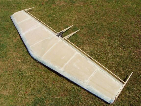
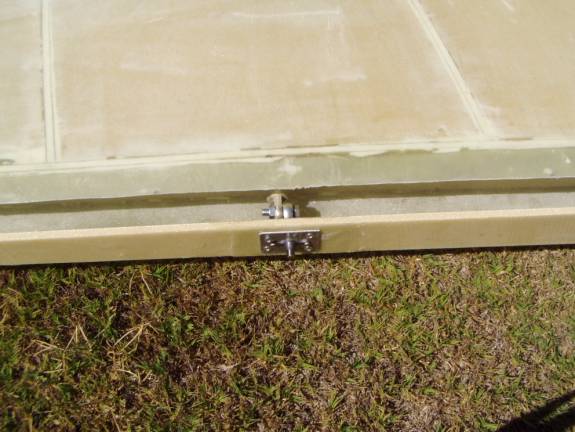
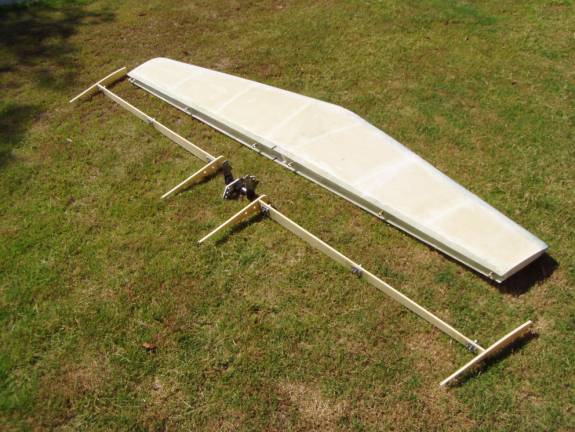
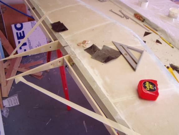
Horizontal Stab with Elevator Frame
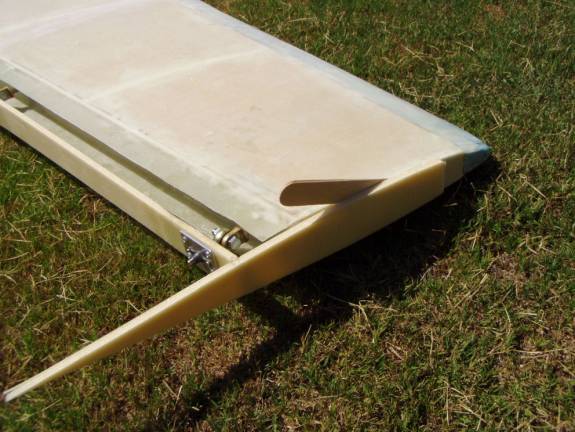
Insure that the entire assembly is square and there is proper 1/4" spacing between the tip ribs and the stab.
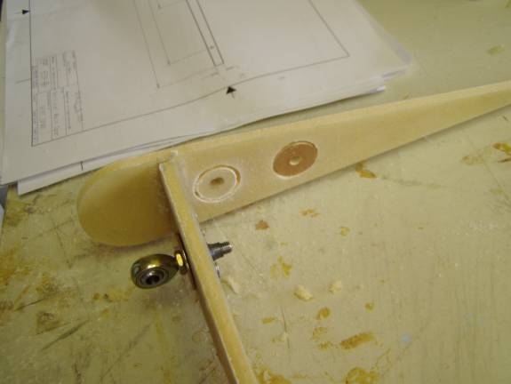
Close up of End Rib
Use inexpensive hardware store bolts until we are ready for final Install
Dissasemble the elevator, being very careful as it is delicate.
Install hardpoints on the inside of the driving rib as was done for the spars.
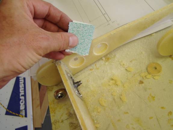
Installing these hardpoints would have been easier if it were done before the ribs were attached to the spar.
While you are installing the hardpoints, if there is extra micro, add radii to the front and back side of each spar where the two ribs are attached. We will be adding layers of carbon fiber to this joint.
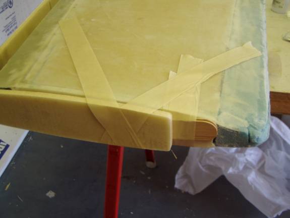
Once the hardpoints have cured, reinstall the elevator to the horizontal stab and secure the ribs into their proper position. Take your time because we are going to permanently attach the ribs to the spar. We do not want any twists or any out of square elements.
Do what ever is necessary to insure the ribs are square, here all I needed was a little tension provided by strips of masking tape. Use a square to insure proper alignment of the dirving ribs.
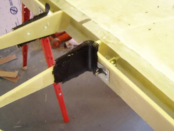
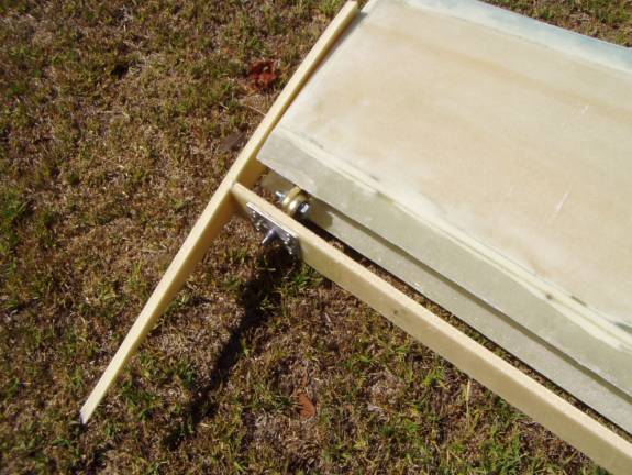
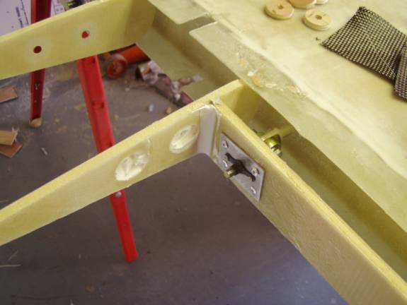
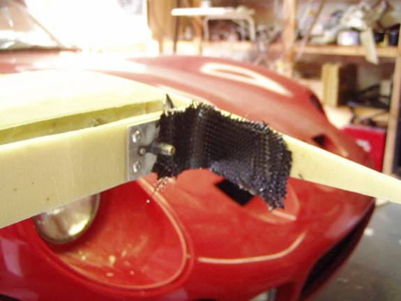
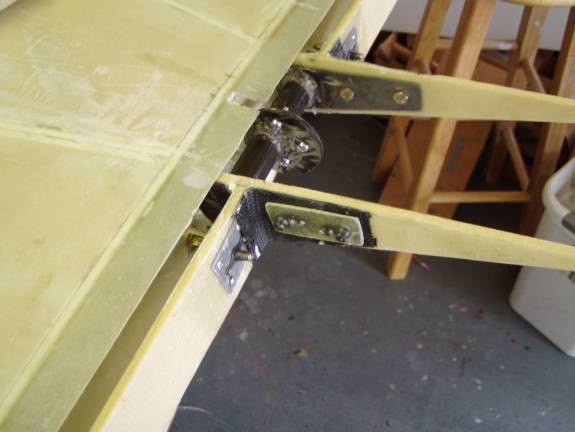
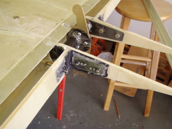
Add four layers of carbon fiber to the two outside joints of the spar to the driving rib and the tip rib. Use decreasing sizes of carbon so you have a feathered edge. The reason that carbon is used in these joints is because of the load carried by the driving rib. In the accompanying photos you see carbon fiber overlapping an aluminum nut plate. this is a no-no. If carbon fiber is going to contact aluminum as in this case, add a layer of fiberglass between the two.
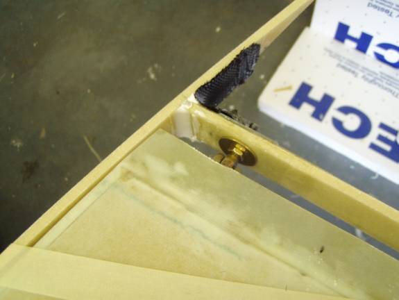
Here you can see the radius on the inside joint. This can not be glassed until the outside cures and the elevator is removed.

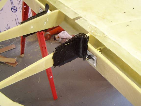
Use 4 layers of carbon fiber on the tip rib as well. this rib joint needs to be strong due the the counterbalance weight in the elevator tip.
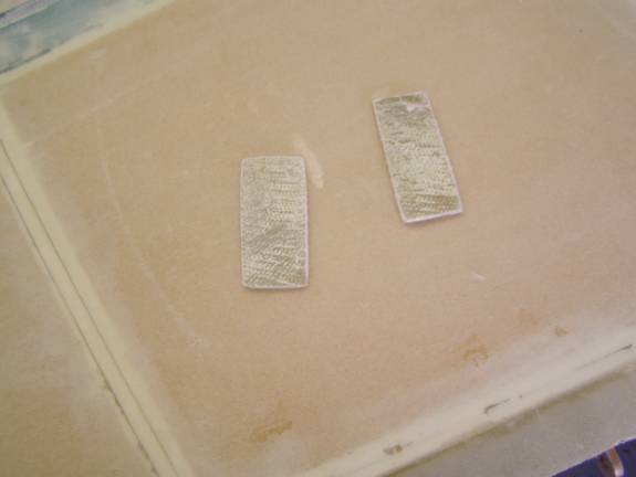
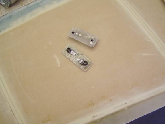
Clamp the nut plates directly to the elevator control horn welement and drill holes to match those in the weldment. Install bolts to hold the nut plates in position as the rivet holes are drilled. then countersink and rivet the nut plates in position. Mark the nut plates, right and left.
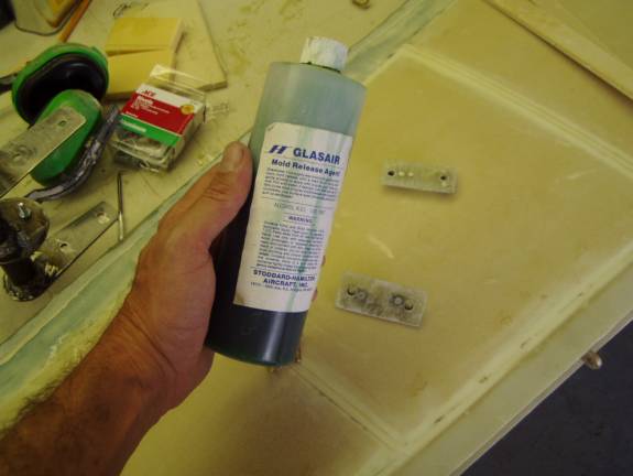
We will use a little mold release on the bolts and nut plates while they are curing so as not to gum up our threads.
Attatch the welements to the elevators and insure the proper position of the entire assembly. Once you are happy with the position of everything prepare to attach the nut plates.
Sand and clean both surfaces and use a thick flox mixture to attach the nut plates. Why are we using fiberglass nutplates instead of aluminum nutplates? Carbon fiber and aluminum do not get along together--aluminum in contact with carbon fiber can corrode. But look the hinge nut plate is covered with carbon fiber in the photo above...remember we added a layer of fiberglass between the two..