Chapter3 - Fuselage
Section 1 - Front Fuselage
Building the Fuselage Support Frame
The forward fuselage section is assembled on a frame, which holds the panels we have already fabricated. The frame is a simple affair utilizing the rigidity of the panels to provide the majority of the support. A 4’ X 4’ piece of ½” MDF is used to create the corner plates and a couple of 2X4s are used to hold it all together. The key to the fuse frame is the corner plate. These establish the 82 degree angle of the fuse sides and the fuse bottom as well as provide the spacing and support for the foam strips that create our complex curved radius section.
Print out multiple copies of the corner frame drawing 1:1 and glue them on to sized pieces of ½” MDF. MDF is used instead of other material like plywood for its stability and ease of workability. Do not breath the dust, however as it is high in urea.
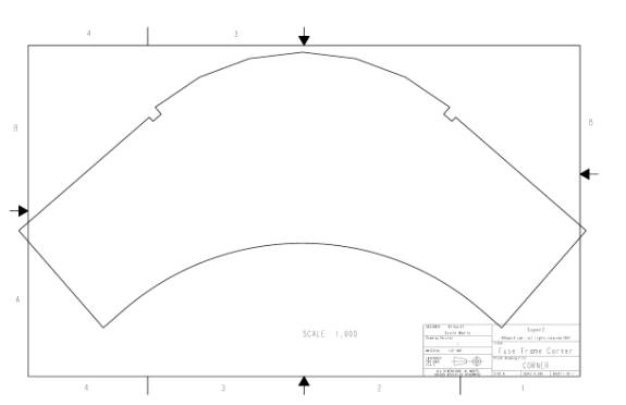
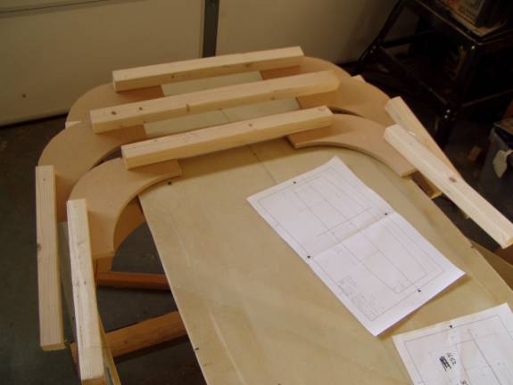
1:1 Drawing of the fuselage corner plate – make
10
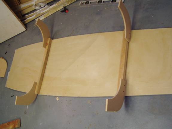
The corner plates are symmetrical so it does not matter what side is up and which is down. Also notice that there is a notch at the transition from the panel edge to the radiused edge. The panel edge will rest up against this notch. We will talk about this edge notch later.
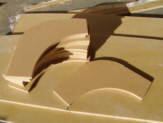
Use a saber saw or band saw to cut out ten corner
plates.
Once we have our corner plates we need to rip a couple of 2X4s to produce some 2X2s. We will end up making 5 formers referred to as former A through E with former A at the firewall location and former E at the end of the forward fuselage section.. When we made our panels we should have marked the ten points that defined the panel shape. If not, go back and use a sharpie and mark these points; five along each top and bottom edge. The line can be seen in the above photo at the lower left of the single corner plate on the fiberglass panel.
Two of the formers will become a floor stand, former B and former D. Pull up the drawings for these two formers- FORMER_B, FORMER_D.
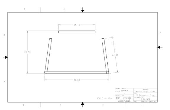
Former B drawing
Above is the drawing of former B. Notice that the corner plates are not shown in drawing. This is to make it easier to see the length of the four 2X2s that make up the former. These lengths are approximate. Measure the width of the fuselage bottom panel at the location of Former B; it should be about 24.5” wide as shown in the drawing, if it is off a bit that is OK, cut the top 2X2 so that the two corner plates have their edge notches hang over the edge on each side of the panel. Secure the corner plates to the top 2X2 with a couple of 2” sheet rock screws. See the two photos below for comparison to yours.
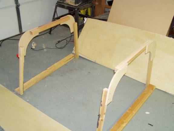
Former B and Former D top sections
Former B and Former D top section set into place
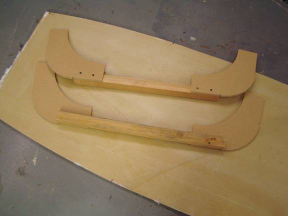
Next, cut the former sides. Again the drawing is only approximate. My garage floor is level side to side but it drops about a ½” every 8 feet from front to back. Since former B and former D are about 42” apart, the side legs for one of the formers had to be a bit longer to maintain the fuse frame in level. Cut the side and bottom 2X2s and assemble the two formers. Place them 42” apart and use a laser level to level them up in both directions. The top of former B and Former D should be level with each other.
Completed Former B and Former D leveled
This would be a good time to mention that we do not want to permanently fix the panels to the formers yet because we will have a little fiddling to do and we will want to protect the formers and floor with a drop cloth before we start our fiberglass work. When the formers are complete we will spread a plastic drop cloth on the floor and we will cover each former with plastic so that any dripping resin will not permanently attach the formers to the fuselage bottom.
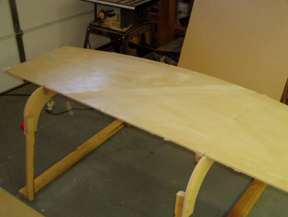
Test fitting the fuselage bottom
The photo above shows the fuselage bottom being test fit to the frame. Note that the lines we have marked on the fuse bottom are used to line up with the edges of the former corners.
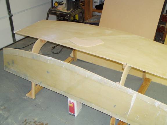
Test Fitting the fuselage sides to the frame
In the above photo the side panel is test fit. The former B and former D should be vertical and will need to be leveled later. Now is the time to insure our marking on our panels are correct.
The remaining 3 formers are made in a similar manner with the exception that they do not reach the floor and they are constructed with only 3 2X2s each. Measure the width of the fuselage bottom at the location of the three formers and cut the 2X2s to this length. Attach two cormer plates to result in the former tops. Cut 16” lengths of 2X2 and attach them to the sides of the cormer plates to give us the three remaining formers.
Formers A,C,E
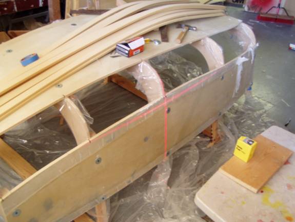
Assembling the Panels on the Frame
Once you have test fit all five formers and are happy that everything will line up and level correctly, cover the floor and formers with plastic. Then using fender washers and 2 1/2" sheet rock screws attach the panels to the formers. Note that the screws attaching the bottom panel are inboard of the joggle. We will be glassing inside the joggle and do not want to cover our screws. This is also true of the joggles on the side panels next to the radius, put the screws clear of the joggles. The screws that hold the side panels to the formers that are closest to the floor can be placed in the joggle area. This will result in less filling later.
Take time to level Everything up.
Using the laser level is an easy way to insure that the whole assembly is level. Insure that each former is vertical and assembly is level side to side.