Chapter 3 - Fuselage
The Super2 fuselage is constructed in several major sections. First, the bottom half of the fuselage is built and is usually referred to as “the boat”. It is built on a form, upside down. After the outside is glassed, it is flipped over, the inside is glassed and bulkheads are added. Then there is a turtle deck, which forms the rear top of the fuselage behind the pilot’s head. The forward deck forms the top of the fuselage in front of the pilot to the firewall. Finally the canopy is built. Our first job is to fabricate the “Boat”.
The fuselage bottom is built on a form upside down. Prefabricated panels are attached to this form and give it much of its rigidity. The major panels consist of last-a-foam glassed on both sides. These panels are fabricated on a flat surface, like a large work table or a garage floor.
The soft lines of the Super2 are due to its radiused edges. These radiused edges are created in two ways. The tailcone radius is a flattened cone and is made by glassing the outside only of the ¼” thick section of the tailcone panels. The section is then ‘folded’ into the desired curve. The forward fuselage bottom corners are compound curves and required a different technique. Even though they are of a constant radius, the fuselage sides and bottom meet in a complex curve moving through two planes. We will build this in a manner similar to that used by a cooper making a wooden barrel. We use multiple strips of ½”thick foam laid side by side like staves in a barrel, then sand them from a hexagonal shape to a smooth curved surface.
Our first job is to create all of the flat panels that will be used to fabricate our “Boat”.
Section 1 - Forward Fuselage Half
Fuselage construction - Overview
The panels that will be prefabricated are as follows:
- The forward side panels
- The forward bottom panel
- The four ½” thick foam sheets are cut for the tail cone
- The two ¼” thick foam sheets are cut for the tail cone
- The tail cone is assembled
Once the panels have been created we will build our form. We will screw the three forward panels to the forms, the two sides and bottom, to create a rigid structure. Then strips of ½” foam are temporarily glued to the forms between the sides and bottom to form the radius between the bottom and sides-our barrel staves. We will use a custom made sanding tool to create a nice radius.
The tail cone has already been fabricated with the exception of glass on the inside surface of the ¼” foam. This will allow us to bend the tail cone into shape and secure it to our forms. We glass the joints and the inside radius then flip the assembly over. We install bulkheads and end up with a rigid fuselage bottom.
Panel Fabrication – Forward Fuselage Side
Before we begin fabricating our panels, we need to understand the use
of joggles. We will join the panels together with fiberglass tape
in depressed areas at the edges of the panels called joggles. The
joggle depressions are made in our foam blanks by a simple sanding block. The
first panel made will be the forward fuselage side. It is the smallest
and simplest. Pull up the drawing for the forward fuselage side
and find the two datum axis.
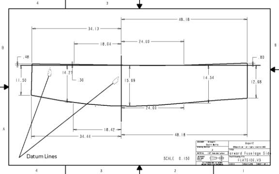
Forward Fuselage Side Drawing
All of the dimensions on the drawing are referenced to these two datum lines. Protect your garage floor with a large sheet of plastic drop cloth. Start by laying out a 18” X 96 “ piece of 4.5 lb. Last-a-foam on top. Go ahead and cut 6 inches off of the long edge of two pieces of 24” X 96” last-a-foam to make the two side blanks. Lightly mark the datum lines with a pencil using a laser level or a long straight edge on one of the sheets. The lengthwise datum line should be drawn about an inch from the top edge of the sheet. The vertical datum line is drawn about 35” from the left edge of the panel. There are ten points that define the shape of the fuselage side, 5 along the top and 5 along the bottom. Using the dimensions shown in the drawing mark these on the foam blank. Use small nails to mark these points—if we use pencil, the points will be erased when we sand out joggles into the foam. The top edge consists of three straight lines and the bottom edge consists of a single smooth curve. Lightly mark the outside edge with a pencil on the blank panel. The orientation of the above drawing has the front of the aircraft is to the left, and the rear to the right. Draw a second line 2” above the bottom curve. This defines the upper edge of our joggle. Use a 2.5” X 2.5” square block of wood with sandpaper affixed to lightly sand a joggle verhanging .5” outside the bottom line. The joggle should only be about 1/16” deep. Use a small piece of 1/16” aluminum to lay into the joggle to insure the proper depth. Fair the small edge of the joggle trough with the top edge. Note" The pdf drawing looks like the fuselage sides are make of straight lines that do not correspond the the dimensioned locations. This is an aberation of the CAD program. Only use the points that are dimensioned.
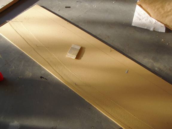
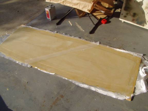
Sanding in the Joggles
This photo shows the joggles sanded into the sheet of foam for a fuselage side. A special joggle sanding tool is shown on the foam, it only allows a joggle to be sanded a limited distance into the foam.
Repeat this process and create a joggle at the rear of the panel and the top of the panel. A joggle is not required on the left side (firewall side) of the panel. Align the first panel atop the second panel and push the nails all the way through both panels. You have now two identical panels. Use a pencil to mark the location of the holes on both sides of both panels. These 10 holes will fill with micro and need to be drilled out later. Set the second panel aside and let us finish off the first. Get out your shop vac and completely vacuum the sanding dust from the panel—it needs to be absolutely dust free before we can slurry.
Measure out the cloth. We will use one layer of UNI and one layer of BID on the outside and one layer of BID on the inside. Place the UNI with the major glass strands running from the front of the aircraft to the back (left to right in the drawing). If more than one piece of UNI is required, the ends must have about a 2” overlap, but no overlap is required if laid side to side. Measure out the BID for both sides. The glass is laid out on the 45 degree bias front to back. All BID sections must overlap by at least an inch. Mark the glass sections and set aside. Use gallon size zip lock bags labeled with a sharpie marker to hold the glass sections.
We are ready to perform the fiberglass layup. Be prepared to move
swiftly, but confidently. This is going to be our largest layup
to date. Pull all of your equipment together, mixing tools, squeegee,
brushes, gloves, cleaning supplies, etc. Slurry the entire foam panel
and lay out the UNI. Generously wet out with epoxy resin. Apply
the BID and wet it out with epoxy. Mix moderate batches of resin and work from the inside
of the panel outward. Use the squeegee to hurry the wetting out
process along. When the glass is fully wet and you are satisfied
with the way the glass lies and there are no air bubbles, use paper
towels to lift some of the excess resin from the panel. Wipe with the
major thread grops, from the inside of the panel to the edges (this would
be 45 degrees to the axis of the panel since we are using 45 degree bias
glass) Obtaining the proper amount of resin is a balancing act. Do
not dry areas so that the glass strands look dull and lift up, but do
not leave glossy pools of resin either. When you are satisfied
with the layup, you can lay peelply over the layup for a smoother surface. Again,
start in the middle of the panel and work your way to the edge. Multiple pieces of peel ply are easier to manage than one large sheet. When
satisfied, let the panel cure.
Congratulations, you have created your first fuselage panel layup. After
the panel is fully cured, peel off the large sheet of peel ply. It has been said before, but it is good to reiterate
here. Always remember to remove the peel ply, for if you do not
the joint will fail. Relocate the 10 datum points, drilling 1/16” holes
where the nail holes were marked on the back.
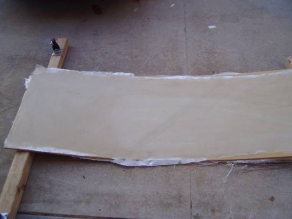
Flip the panel over and support the left and right edges about 3 inches above the ground at each end—a 2X4 on edge works well. This will approximate the curvature of the aircraft sides. Slurry and glass with a single layer of BID on the 45 degree diagonal. Again insure that you have at least one inch of overlap between pieces of BID. Let cure. Use a saber saw or cut off wheel to cut the panel out along the lines you made on the outside of the panel. Set aside.
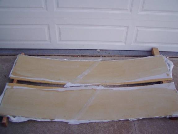
Support Ends 4" in the Air
Now build a second fuselage side, but remember to build the opposite side. If you build a pilot side the first go around, remember to build a co-pilot side now.
The forward fuselage bottom is fabricated in a manner almost identical to the fuselage sides. When you fabricated the fuselage sides you used less than a full sheet of last-a-foam—you cut 6” off to get a piece 18” wide. Take this 6” strip and attach it to the long side of another piece of 24” X 96” last-a-foam. Use a thick glass bubble mixture to bond the sheets together. Be careful not to get too much squeeze out, this could cause a bump in our panel later.
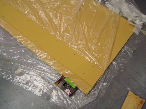
Bonding Sheets Together
Layout the datum lines as we did before with the middle datum line going
right down the long axis of the panel. Locate and mark with small nails
the 10 points that define the shape of the bottom panel.
Glassing Bottom Panel
The sides are continuous curves passing through these points on each side. Create joggles in the long sides and the aft side of the panel as we did with the fuselage sides.
Support Ends 4" in the Air
When glassing the inside of the panel, block up the ends 4” to create the approximate curve of the fuselage bottom. Again, a 2X4 on edge works well for this.
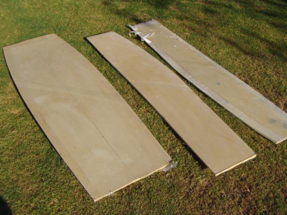
Three Finished Panels