Chapter 8 - Finish the Wing
Section 3 - Ailerons
Ailerons
Aileron construction, installation, control linkage hookup, and aileron counterbalance fabrication are described in this section. The ailerons are cut from full length upper and lower aileron panels. The forward shear webs are integral parts of the lower aileron panels.
Preparing the Outboard wing section for aileron installation
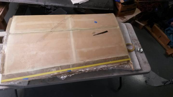
Trim the wing skin extending past the rear spar.
For proper fit of the ailerons, the trailing edge must be perpendicular to the wing chord line, and the upper surface trailing edge must also be straight. Masking tape (stretched for straightness) along the forward side of a chalkline makes a more permanent and more visible reference line for sanding.
Preparing to trim wing skin -inboard
On the inboard side the wing skin extends 1.75 inches behind the rear face of the wing rear spar as shown below.
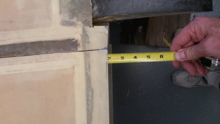
The outboard most rib is required to align the ailerons. The aileron is aligned between the flap in the up position and the outboard most rib that extends behind the wing rear spar.
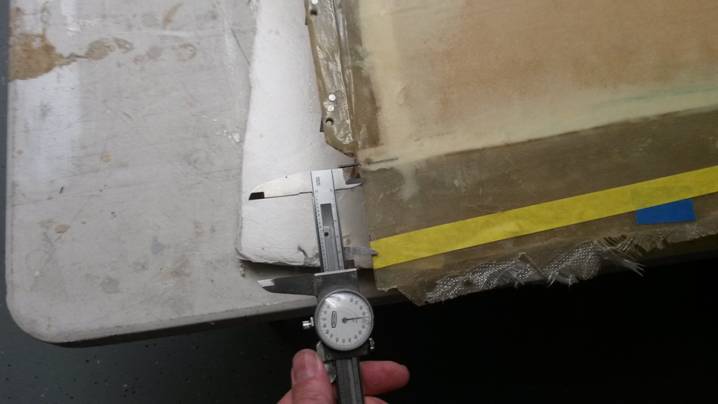
Preparing to trim wing skin – outboard side
On the outboard side the wing skin extends 1.5 inches behind the rear face of the wing rear spar as shown below.
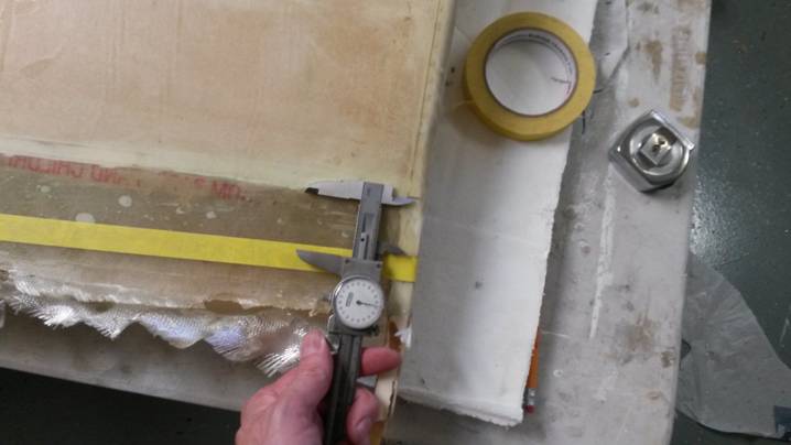
Ready to trim Wing skin
Trim both the top and bottom wing skins in the same manner. To insure the top and bottom wing skin are trimmed to the same distance, use a level to level the chord line, then insure the top and bottom skin are vertical as shown below.
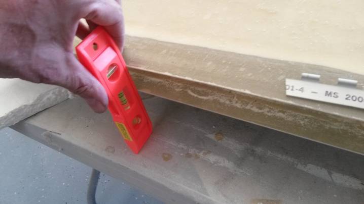
Insure top and bottom skin are trimmed to the same dimension
Only use MS20001-4 hinge for the ailerons as it is an extruded hinge and is much stronger than formed hinges.
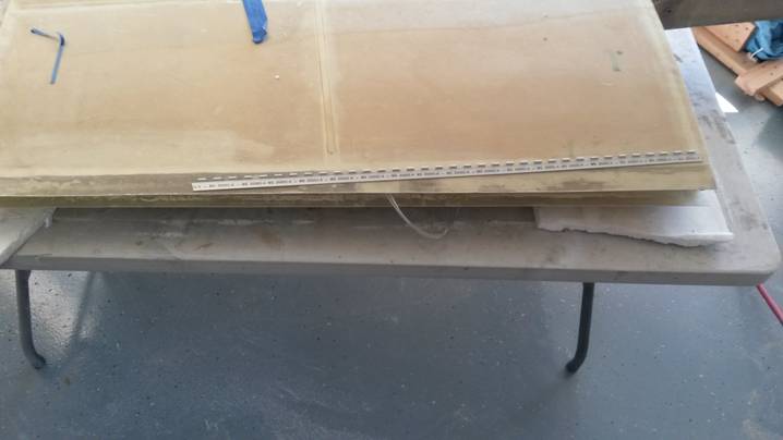
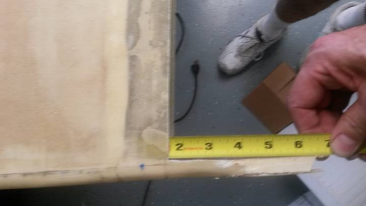
Length of hinge atop trimmed wing section.
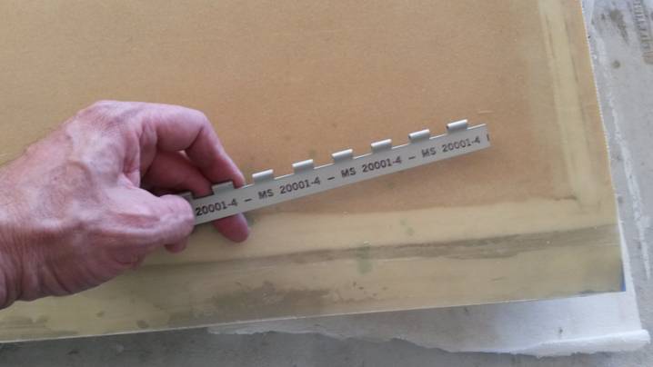
Only use MS20001-4 extruded hinge
Hinge sections are 8” long and are positioned 1.25 in inboard from the wing tip rib on the outboard side, and 1 inch out from the inboard edge on the inboard side.
From the supplied MS20001P4 hinge stock cut four pieces 8" long for the aileron hinges. Remove the hinge pin before cutting the hinge material. Since one hinge half will be inverted relative to the other half, cut the hinge material so that the knuckles at both ends are half their original length (1/4" long instead of 1/2" long). When cut this way, one hinge half can be inverted without destroying the symmetry of the hinge assembly. Cut the hinge pins 1-1/2" longer than the hinge halves. The extra length will be used to secure the hinge pin later. On one end of each hinge pin, grind a (dull) point approximately 1/4" in length to ease insertion of the pin. On the opposite end, form a locking arm by bending the last 3/4" of the hinge pin 90°.
Do not drill any mounting holes at this time.