Installing Rear Rudder Cable Exit Guides. We are now going to punch some holes in the rear fuselage to allow the rudder cables to exit. We will fabricate these cable exits from 1/4" Nyflow tubing. This tubing is very durable and is intended for use as a bushing for cabling.
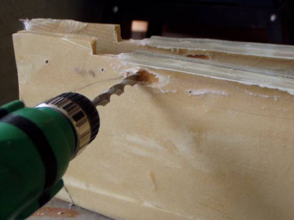
Step 1: Cut two 5” lengths of ¼ Nyflow tubing as rudder cable exits. Step 2: Drill a 3/8” hole through the OUTER skin ONLY located 1” forward of the rear edge of the horizontal stab and .75” below the horizontal tail flange.
Step 3: Then continue drilling the hole through the INNER skin with the drill oriented forward, parallel with the aircraft centerline. It is fine if the hole is greatly oversized as this will be filled in with micro.
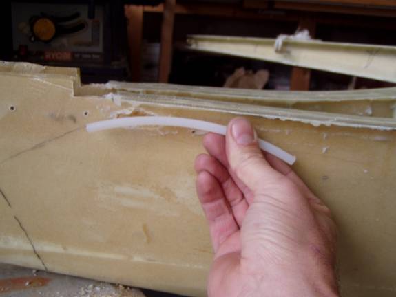
Step 4: Test fit the tubing in the holes you have made in the fuselage sides.
The orientation of the tube should be such that it curves downward as shown above, and is as straight as possible when viewed from above, aligned with the aircraft center line. In the above photo you can see a pencil mark drawn on the fuselage side representing the angle of the rudder cables running from the exit tube to the rudder control horn.
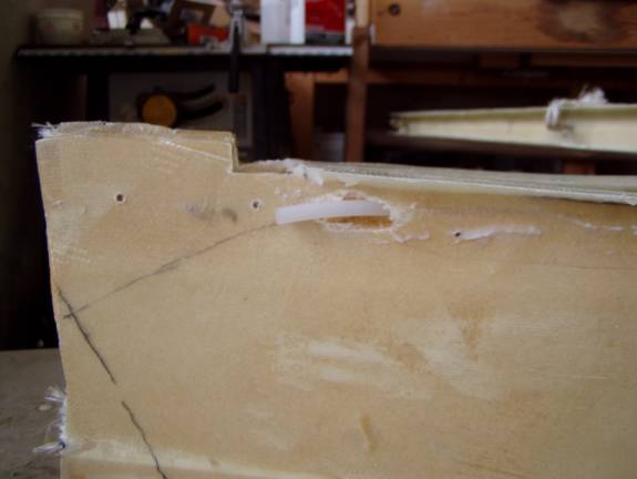
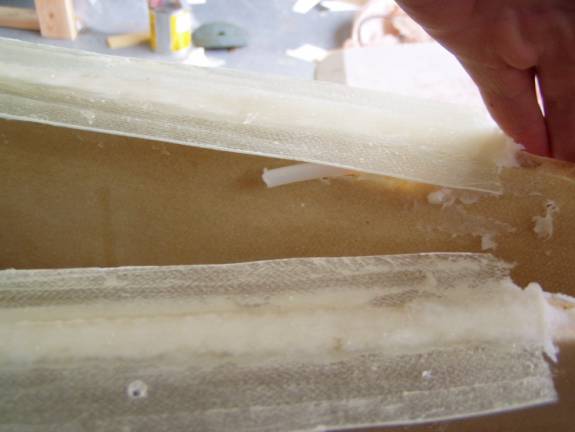
Above is the properly positioned exit tube as seen from the outside and the following photo shows it from the inside.
Step 5: Once the rudder exit tube is properly positioned and you are happy with the hole, scuff the outside of the tube with coarse sand paper. Use masking tape to wrap each end of the tube to seal it temporarily. Step 6: Mix up a batch of thick micro, fill both holes with micro, coat the outside of the tube, then press the tube through the micro filled hole, refilling it with micro as the tube is inserted. Position the tube as you did in the practice run, then clean the excess micro to form a nice fillet on the inside and outside. Let cure. |


