Chapter 2 - Fabricating the Tail
Section 1 - Horizontal Stab Assembly
Horizontal Stabilizer Assembly
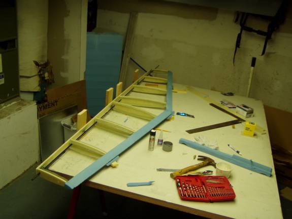
Once the horizontal tail ribs, horizontal stab spar, and the horizontal stabilizer leading edges are completed, the horizontal stabilizer can be assembled. Clear your workspace so the stabilizer can be worked on near the edge of the table. Take this opportunity to level up the table. Lay the spar along the edge of the table and mark the location of the four inboard hinge points onto the table. Secure pieces of 1” X 4”s as shown to the edge of the work table as support blocks. Set your laser level across the table from the edge to support the rear spar so it can laze the entire length of the spar. The recommended placement of the laser level is shown in the photo.
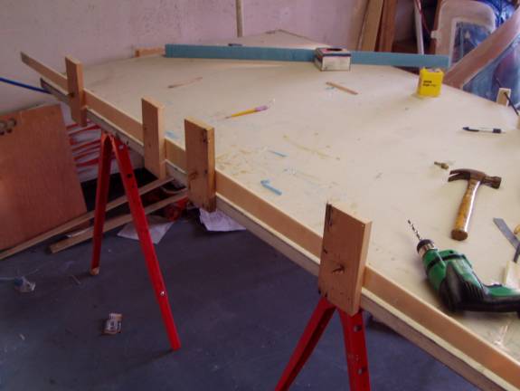
Use a pencilto mark the level line where the laser paints the four support blocks. Use a spacer under the laser level if required to allow room for the spar to be mounted above the level of the table.
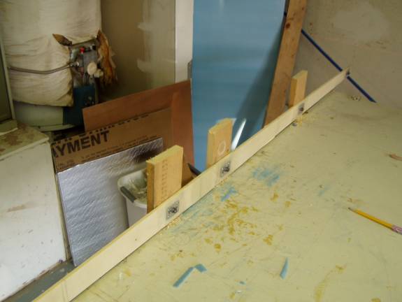
Hold the spar against the support blocks and mark the locations of the four hinge holes. Drill and mount the rear spar to the mounting block and insure it is level with the laser level line passing through the center of the spar and the center of the hinge bolts. Use the hinge eye bolts to attach the spar to the support blocks.
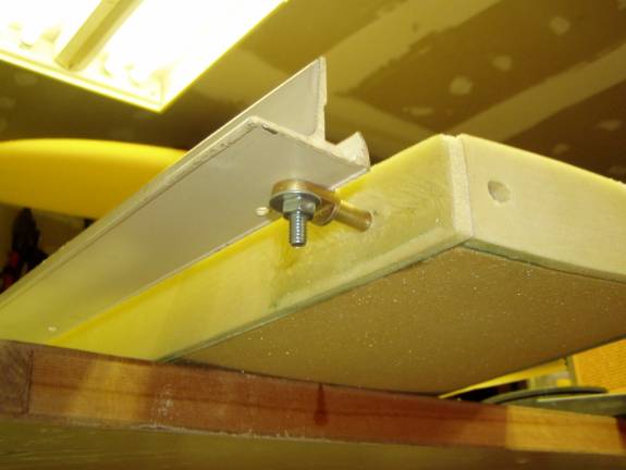
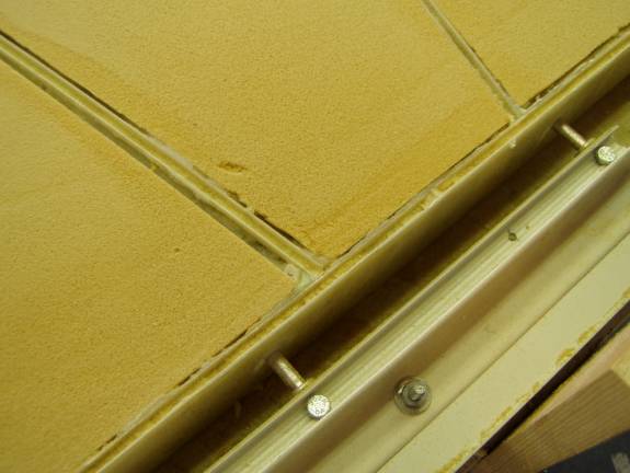
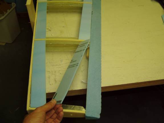
A better way to hold the trailing edge true is to use a piece of angle aluminum. Turn the eye bolts 90 degrees to the final mounting direction as shown above. The center of the hinge pivot point, that is, the center of the eyebolt hole, should be 1.25” from the rear side of the horizontal spar. Install all of the eyebolts and adjust them to this dimension. If the angle is bolted against the flange of the eyebolt it holds the alignment of the elevator pivot axis true in both planes.
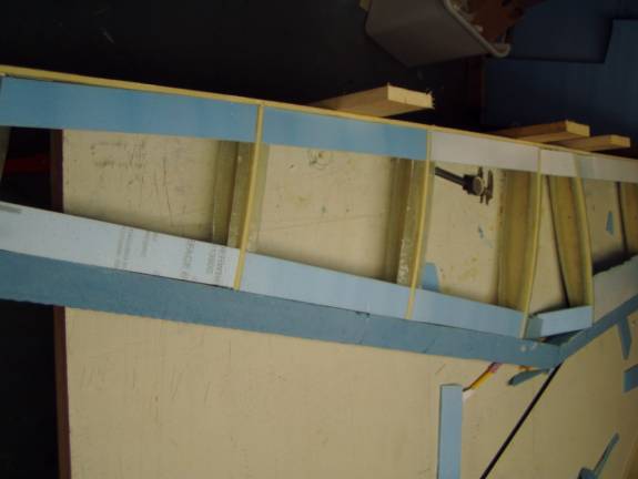
There are two holes in each of the horizontal ribs that can be used to align and level the horizontal ribs. The photo shows a carbon fiber shaft running through the holes to temporarily hole the ribs in alignment. It is also possible to sight down through the ribs to insure they are in alignment. Both the spar and the leading edges were marked for the rib locations. Use these to align the ribs.
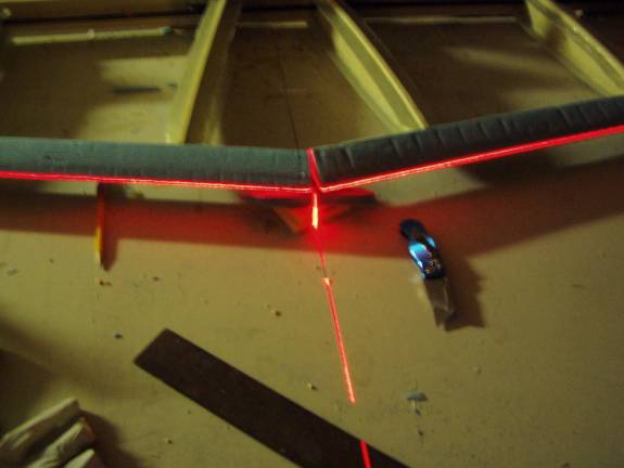
Use the laser level to align the ribs and leading edge. Use spacer
blocks of foam to level the complete assembly. Once the assembly
is completely level and all parts fit properly begin gluing the assembly
together. Mix up a batch of 1 hour epoxy and flox, just mix up
enough for a couple of ribs at a time. If you mix up too much it
can easily exotherm and be too hard to work with. Use this mixture
to glue the ribs to the leading edge and the spar. A Cyanoacrylic
super glue (CA) with a CA accelerator is the best way to hold the ribs
in place while the epoxy cures.
Use the tip of a gloved finger to radius the attachment joint at each end of the ribs with the flox and epoxy mixture. Later we will glass the ribs in.
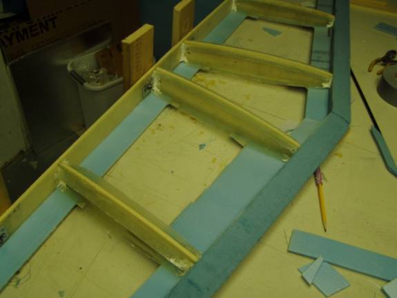
Once the ribs are glued in place, flanges are added to the leading edge
and spar. This is done by taping a piece of foam or cardboard
to the leading edge and spar across the flanges on the ribs. Be sure
the foam or cardboard has a mold release of some sort so the flanges
do not stick to them.
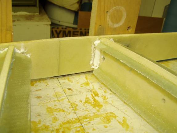
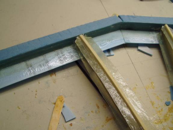
Here strips of ¼” thick polystyrene foam are used to create temporary ledges to layup flanges upon. Cut the strips to fit between the ribs resting upon the existing flanges on the ribs.
The fan-fold foam used here to create the flanges is cheap, easy to get at any home improvement store like Home Depot and has a plastic sheeting on each side that acts as the mold release.
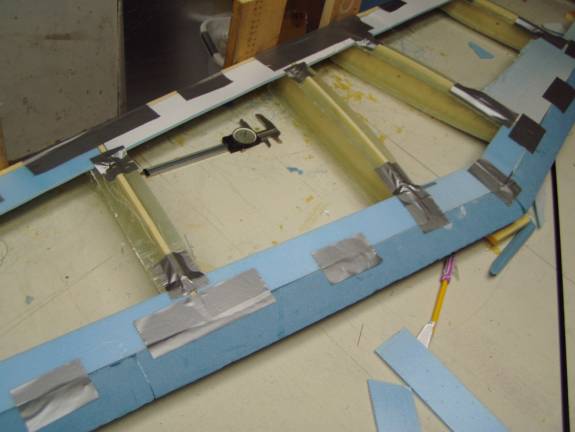
Use duct tape to temporarily hole the flange strips in place. Be sure to fully support them between the ribs, along their edge and at the back to the ribs.
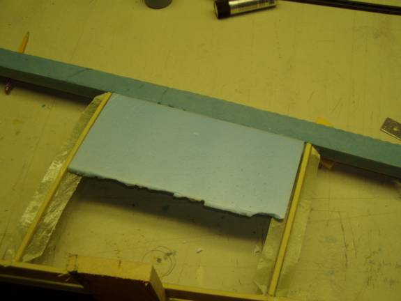
Once the flange strips are securely in place, flip the horizontal stab over and again secure it to the 1” X 4” support blocks. Re-level the assembly with the laser level. Cut strips of fiberglass 1.5 to 2” wide as was done for the rib flanges.
Layup two layers of BID to create flanges as was done for the ribs. Let the epoxy cure, then remove the flange strips and trim the resulting flanges. We only need to create flanges for one side because we will have access to the first side sheeted. The last side, the side that closes out the horizonal stab will use these flanges. We are now ready to skin the horz. stab.