 |
|---|
Elevator BellcrankThe elevator control system consists of a stick assembly mounted under the seat, which is attached to an elevator bellcrank mounted at the aft end of the control tunnel. There is a push rod attaching these with a rod end at both ends. The bellcrank then has two elevator cables that run back to the elevator itself. The top cable runs up over a pulley in the vertical stabilizer in order to clear the horizontal stab. The lower cable is a straight run back. There are turnbuckles in the cables to adjust the proper up and down deflections and allow for proper tensioning of the system. There are two bolts that pass through the control tunnel that the bellcrank hits up against at both ends of it travel that act as elevator stops.
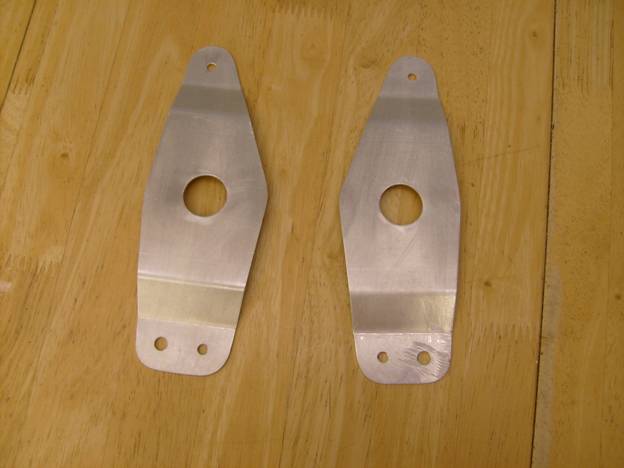
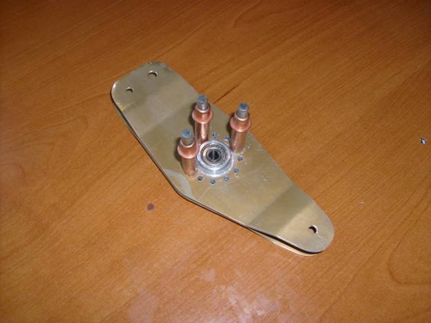
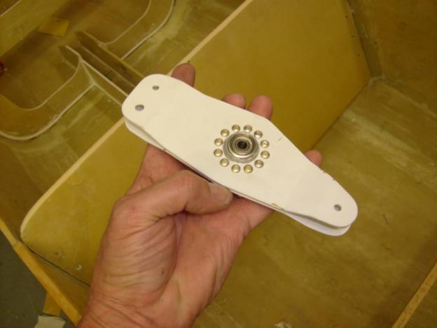
The finished bellcrank has three holes, two smaller ones and one larger one. The larger hole is mounted down and toward the front of the aircraft. A rod bearing is bolted here with an AN4 bolt and connects to the elevator control tube that will attach to the control stick. The two smaller holes will have AN3 bolts with castle nuts and cotter pins through them. Shackles will then attach to these bolts and in turn the control cables for the elevator.
PREVIOUS<---------------Manual Home ------------------>NEXT |


